Display panel and display device
A technology for display panels and substrates, which is applied in nonlinear optics, instruments, optics, etc., and can solve the problems of low contrast in display devices
- Summary
- Abstract
- Description
- Claims
- Application Information
AI Technical Summary
Problems solved by technology
Method used
Image

Examples
Embodiment 1
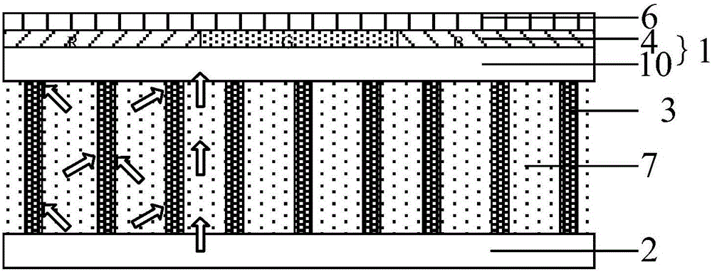
[0038] Please refer to Figures 1 to 10 , this embodiment provides a display panel, including a first substrate 1 and a second substrate 2 oppositely arranged, and a plurality of reflective structures 3 are arranged between the first substrate 1 and the second substrate 2; the second substrate 2 is used for The light emitted by the light source is transmitted; the reflective structure 3 is used for at least one total reflection of the received light transmitted by the second substrate 2 to form outgoing light; the first substrate 1 is used for transmitting the outgoing light.
[0039] It should be noted that the display panel of this embodiment is a display panel added with a color-changing material 7 .
[0040] Please refer to figure 1 ,From figure 1 It can be seen from the figure that the first substrate 1 and the second substrate 2 are arranged opposite to each other, and a color-changing material 7 and a plurality of reflective structures 3 are arranged between the first...
Embodiment 2
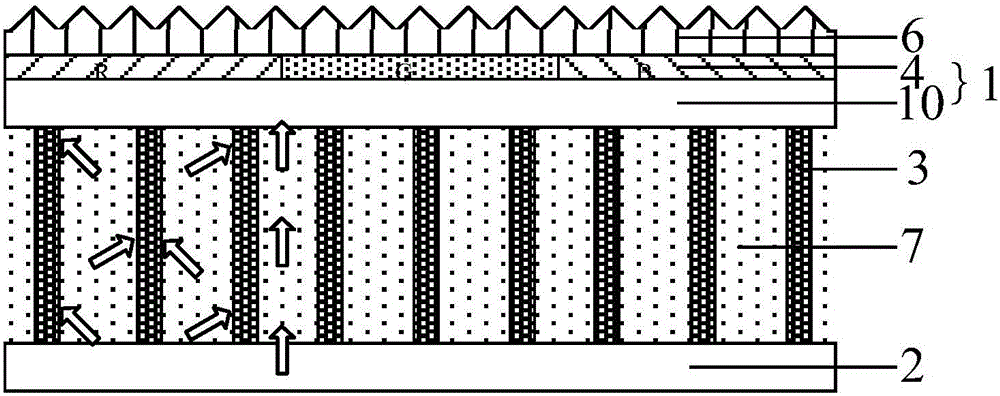
[0066] Please refer to Figure 11 and Figure 12 , this embodiment provides a display panel, including a first substrate 1 and a second substrate 2 oppositely arranged, and a plurality of reflective structures 3 are arranged between the first substrate 1 and the second substrate 2; the second substrate 2 is used for The light emitted by the light source is transmitted; the reflective structure 3 is used for at least one total reflection of the received light transmitted by the second substrate 2 to form outgoing light; the first substrate 1 is used for transmitting the outgoing light.
[0067] It should be noted that the display panel of this embodiment is a display panel added with a color-changing material 7 .
[0068] Please refer to Figure 11 ,From Figure 11 It can be seen from the figure that the first substrate 1 and the second substrate 2 are arranged opposite to each other, and a color-changing material 7 and a plurality of reflective structures 3 are arranged bet...
Embodiment 3
[0084] Please refer to Figure 13 , the present embodiment provides a display panel, which has a structure similar to that of the display panel in Embodiment 2. The difference between it and Embodiment 2 is that the display panel also includes a The reflective structure 3 corresponds to the support body 5 , the reflective structure 3 on the second substrate 2 is located on the support surface of the corresponding support body 5 , and there is a preset angle between the support surface and the second substrate 2 .
[0085] From Figure 13 It can be seen from the figure that a support body 5 is provided on the second substrate 2, the support body 5 has a support surface, and a reflective structure 3 is provided on the support surface, and there is a preset angle between the support surface and the second substrate 2, to tilt the support surface. Preferably, the reflective structure 3 on the support surface corresponds to the interval between two adjacent reflective structures ...
PUM
 Abstract
Description
Claims
Application Information
 - R&D
- Intellectual Property
- Life Sciences
- Materials
- Tech Scout
- Unparalleled Data Quality
- Higher Quality Content
- 60% Fewer Hallucinations
Browse by: Latest US Patents, China's latest patents, Technical Efficacy Thesaurus, Application Domain, Technology Topic, Popular Technical Reports.
© 2025 PatSnap. All rights reserved.Legal|Privacy policy|Modern Slavery Act Transparency Statement|Sitemap|About US| Contact US: help@patsnap.com