Rapid charging circuit and charging method for rechargeable battery

A fast charging and rechargeable battery technology, applied in battery circuit devices, secondary battery charging/discharging, arrangement of multiple synchronous batteries, etc., can solve problems such as slow charging time, heat generation, and poor efficiency

Active Publication Date: 2016-10-12
SHENZHEN WISEPOWER INNOVATION TECH
View PDF4 Cites 15 Cited by
  • Summary
  • Abstract
  • Description
  • Claims
  • Application Information

AI Technical Summary

Problems solved by technology

The existing charging technology has slow charging time, poor efficiency, and severe heat generation

Method used


Image

  • Rapid charging circuit and charging method for rechargeable battery

Examples


Embodiment Construction

[0027] The present invention will be described in further detail below in conjunction with the embodiments and with reference to the accompanying drawings.

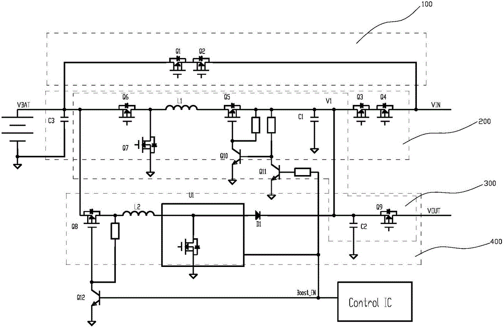
[0028] A fast charging circuit for a rechargeable battery, refer to figure 1 , including a first charging circuit 100, a second charging circuit 200 and a control IC connected in parallel between the positive pole of the battery VBAT and the input terminal VIN of the power adapter, and the battery VBAT is a lithium battery with two cells connected in series;

[0029] The first charging circuit 100 is provided with at least one first switching tube to control its on-off, and the first switching tube is controlled by the control IC; in this embodiment, the first switching tube includes The first MOS transistor Q1 and the second MOS transistor Q2 that control its on-off on the 100, the first MOS transistor Q1 and the second MOS transistor Q2 are controlled by the control IC;

[0030] The second charging circuit 200 includes...


PUM


Abstract

The invention discloses a rapid charging circuit and charging method for a rechargeable battery. The rapid charging circuit comprises a first charging circuit and a second charging circuit which are connected between the positive electrode of the battery and the input end of a power supply adapter in parallel, and a control IC, wherein the first charging circuit is provided with at least one first switching tube for controlling the on-off of the first charging circuit; the first switching tube is controlled by the control IC; the second charging circuit comprises a sixth MOS transistor, a first inductor and at least one third switching tube which are connected between the positive electrode of the battery and the input end of the power supply adapter in series in sequence; the connection point between the sixth MOS transistor and the first inductor is connected with the negative electrode of the battery through a seventh MOS transistor; the connection point between the first inductor and the third switching tube is connected with the negative electrode of the battery through a first capacitor; a third capacitor is connected with the two ends of the battery; and the sixth MOS transistor, the third switching tube and the seventh MOS transistor are all controlled by the control IC. The rapid charging circuit has the advantages of improving the charging efficiency, solving the heating problem in the charging process, improving the charging speed, and satisfying the charging requirements of various kinds of mobile phone terminals.

Description

technical field [0001] The invention relates to a charging circuit, in particular to a fast charging circuit and a charging method for a rechargeable battery that can improve charging efficiency, solve the problem of charging heat, increase charging speed, and meet the charging needs of various mobile phone terminals. Background technique [0002] With the popularity of mobile terminals, more and more attention has been paid to the charging time of mobile terminals, and users hope that their mobile terminals have a short charging time and a long battery life. The existing charging technology has slow charging time, poor efficiency and serious heat generation. Contents of the invention [0003] In order to overcome the shortcomings of the prior art, the purpose of the present invention is to provide a fast charging circuit for rechargeable batteries that can improve charging efficiency, solve the problem of charging heat, increase charging speed, and meet the charging needs...

Claims


Application Information

Patent Timeline
Patent Type & Authority Applications(China)
IPC IPC(8): H02J7/00H01M10/44
CPCH01M10/44H02J7/0013Y02B40/00Y02E60/10
Inventor 钟传富李昊林国锋
Owner SHENZHEN WISEPOWER INNOVATION TECH
Why Eureka
Try Eureka