
Charging pile output parallel controller, charging pile parallel charging system and method

A charging method and technology of charging piles, which are applied in charging stations for charging mobile devices, charging/discharging of secondary batteries, charging stations, etc., can solve problems such as inability to quickly replenish electricity, idle charging piles, and unusable electric vehicles, etc. Achieve the effects of improving charging efficiency and charging pile utilization, easy to implement, and strong applicability

Inactive Publication Date: 2016-06-15
DELTA GREENTECH CHINA CO LTD
View PDF6 Cites 17 Cited by
  • Summary
  • Abstract
  • Description
  • Claims
  • Application Information

AI Technical Summary

Problems solved by technology

[0002] Charging pile is a device for supplementing electric energy for electric vehicles. At present, the main working mode in the industry is that one charging pile can charge one or more electric vehicles at the same time. This method can effectively improve the efficiency of electric vehicles with small battery capacity. The utilization rate of the charging pile, but this method also has the disadvantages that when the power battery capacity of the electric vehicle is large, the charging time will be very long, and it is impossible to quickly recharge the power, especially with the capacity of the power battery equipped with the electric vehicle. It is getting bigger and bigger. The charging time of the existing charging pile is too small due to the low power. The problem of idle charging piles and waste of charging resources

Method used


Image

  • Charging pile output parallel controller, charging pile parallel charging system and method
  • Charging pile output parallel controller, charging pile parallel charging system and method
  • Charging pile output parallel controller, charging pile parallel charging system and method

Examples


Embodiment Construction

[0024] The present invention is described in detail below in conjunction with accompanying drawing:

[0025] The invention will now be described in more detail with reference to the accompanying drawings, in which preferred embodiments of the invention are shown, it being understood that those skilled in the art may modify the invention described herein and still achieve the advantageous effects of the invention. Therefore, the following description should be understood as the broad knowledge of those skilled in the art, but not as a limitation of the present invention.

[0026] In the interest of clarity, not all features of an actual implementation are described. In the following description, well-known functions and constructions are not described in detail since they would obscure the invention with unnecessary detail. It should be appreciated that in the development of any actual embodiment, numerous implementation details must be worked out to achieve the developer's sp...


PUM


Abstract

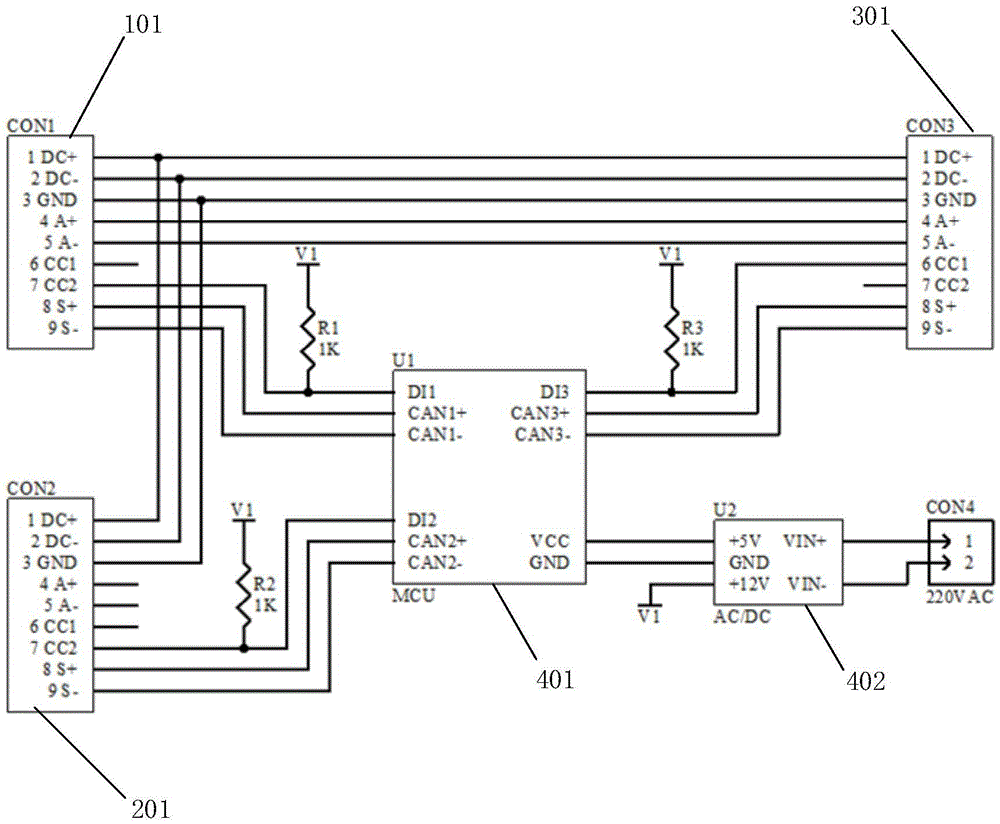
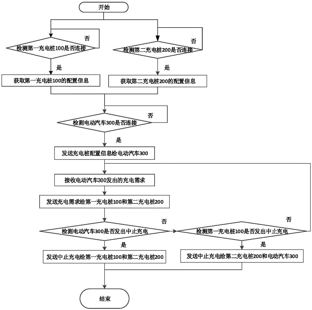
The invention discloses a charging pile output parallel controller. The charging pile output parallel controller comprises a control chip, an electric vehicle insertion gun interface and more than one charging pile insertion gun interface, wherein the control chip is in communication connection with the electric vehicle insertion gun interface and the charging pile insertion gun interfaces; the output circuits of the charging pile insertion gun interfaces are connected in parallel and then are input to the electric vehicle insertion gun interface; the electric vehicle insertion gun interface is connected with an electric vehicle through an electric vehicle insertion gun; and the charging pile insertion gun interfaces are connected with corresponding charging piles through charging pile insertion guns. The charging pile output parallel controller is adopted to obtain charging requirements; the maximum output capacity of multiple charging piles is adjusted in real time to satisfy the charging requirements of the electric vehicle to the highest extent, so as to charge the electric vehicle by multiple charging piles in a parallel output manner, so that the charging efficiency for the electric vehicle and the utilization ratio of the charging piles are improved.

Description

technical field [0001] The invention relates to a charging pile output parallel controller, a charging pile parallel charging system and a method, which are applied in the field of electric vehicles. Background technique [0002] Charging pile is a device for supplementing electric energy for electric vehicles. At present, the main working mode in the industry is that one charging pile can charge one or more electric vehicles at the same time. This method can effectively improve the efficiency of electric vehicles with small battery capacity. The utilization rate of the charging pile, but this method also has the disadvantages that when the power battery capacity of the electric vehicle is large, the charging time will be very long, and it is impossible to quickly recharge the power, especially with the capacity of the power battery equipped with the electric vehicle. It is getting bigger and bigger. The charging time of the existing charging pile is too small due to the low...

Claims


Application Information

Patent Timeline
Patent Type & Authority Applications(China)
IPC IPC(8): H02J7/00H01M10/44
CPCB60L53/11B60L53/305B60L53/31B60L53/64H01M10/44H02J7/0027Y02E60/10Y02T10/70Y02T10/7072Y02T90/12Y02T90/14Y02T90/16
Inventor 刘静戚青山
Owner DELTA GREENTECH CHINA CO LTD
Learn More