Wireless charge receiving device, wireless charge transmitting device and wireless charge system

A wireless charging and receiving device technology, applied in the direction of circuit devices, electromagnetic wave systems, battery circuit devices, etc., can solve the problems of short charging distance and low charging efficiency, achieve the effects of reducing losses, meeting charging needs, and improving charging efficiency

Active Publication Date: 2012-05-30
KUANG CHI INST OF ADVANCED TECH +1
View PDF5 Cites 16 Cited by
  • Summary
  • Abstract
  • Description
  • Claims
  • Application Information

AI Technical Summary

Problems solved by technology

[0006] The technical problem to be solved by the present invention is to provide a wireless charging receiving device, a wireless charging transmitting device, and a wireless charging system for the defects of short charging distance and low charging efficiency in the above-mentioned radio wave charging method of the prior art.

Method used


Image

  • Wireless charge receiving device, wireless charge transmitting device and wireless charge system
  • Wireless charge receiving device, wireless charge transmitting device and wireless charge system
  • Wireless charge receiving device, wireless charge transmitting device and wireless charge system

Examples


Embodiment Construction

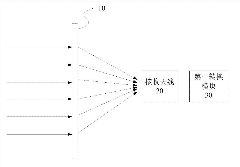
[0029] figure 1 It is a schematic structural diagram of a wireless charging receiving device according to a preferred embodiment of the present invention. The wireless charging receiving device includes a receiving antenna 20 , a first metamaterial convergence module 10 , and a first conversion module 30 .

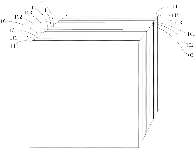
[0030] The first metamaterial converging module 10 is used for converging electromagnetic waves onto the receiving antenna 20; figure 1 A side view of the first metamaterial convergence module 10 is shown in , and its perspective view is shown in figure 2 .

[0031] The first converting module 30 is configured to convert the electromagnetic wave received by the receiving antenna 20 into electric energy, so as to charge the device to be charged.

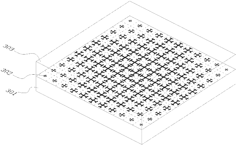
[0032] figure 2 It is a schematic diagram of the three-dimensional structure of the first metamaterial convergence module 10 of the present invention. like figure 2 As shown, the first metamaterial converging module 10 in...


PUM


Abstract

The invention relates to a wireless charge receiving device, a wireless charge transmitting device and a wireless charge system. The wireless charge receiving device comprises a receiving antenna, a first meta-material convergence module and a first conversion module, wherein the first meta-material convergence module is used for converging electromagnetic wave to the receiving antenna; the firstconversion module is used for converting the electromagnetic wave received by the receiving antenna into electric energy so as to charge equipment to be charged. The wireless charge transmitting device comprises a second conversion module and a second meta-material convergence module, wherein the second conversion module is connected with a power supply for converting the electric energy into electromagnetic wave; and the second meta-material convergence module is used for converging the electromagnetic wave output by the second conversion module into planar wave and then transmitting the planar wave so as to be received by the wireless charge receiving device. In the invention, the electromagnetic wave is transmitted in a more centralized way by a transmitting end, so that the loss in anelectromagnetic wave transmission process is reduced, more electromagnetic wave energy can be received by the receiving end, the electromagnetic wave energy can be converted into electric energy as much as possible to increase charging efficiency, and the charging requirements at longer distance can be met.

Description

technical field [0001] The present invention relates to charging technology, more specifically, to a wireless charging receiving device, a wireless charging transmitting device, and a wireless charging system. Background technique [0002] Wireless charging technology is one of the hottest and most potential technologies recently. The existing wireless charging technology mainly uses three methods: [0003] 1) Electromagnetic induction: The current is induced by the primary and secondary coils to transfer energy from the transmission end to the reception end. The main technical core is to charge by generating an induced current between two sufficiently close coils. The disadvantage of this technology lies in the limitation of charging distance, low transmission efficiency and heat generation problem. [0004] 2) Electromagnetic resonance: energy is transferred between coils using inductive or capacitive coupling in the near-field region. High energy transmission efficienc...

Claims


Application Information

Patent Timeline
Patent Type & Authority Applications(China)
IPC IPC(8): H02J7/00H02J17/00H02J50/20
Inventor 刘若鹏季春霖岳玉涛殷俊
Owner KUANG CHI INST OF ADVANCED TECH
Why Eureka
Try Eureka