Antenna arrangement having a fan unit

An antenna system and fan technology, applied to antennas, transmission systems, antenna components, etc., can solve problems such as weakening antenna efficiency

Active Publication Date: 2016-10-12
EBM PAPST ST GEORGEN & -
View PDF6 Cites 7 Cited by
  • Summary
  • Abstract
  • Description
  • Claims
  • Application Information

AI Technical Summary

Problems solved by technology

The main problem is passive intermodulation (PIM=passiv intermodulation), which can be produced, for example, by electrical and electronic components in

Method used


Image

  • Antenna arrangement having a fan unit
  • Antenna arrangement having a fan unit
  • Antenna arrangement having a fan unit

Examples


Embodiment Construction

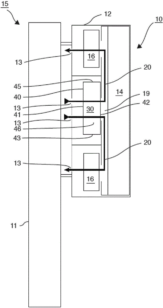
[0063] figure 1 A base station 15 is shown schematically with an antenna system 10 arranged on a support device 11 , for example an antenna mast 11 .

[0064] Such an antenna system 10 is preferably according to the GSM standard, the LTE standard or the UMTS standard such as figure 1 The shown is used in a base station (English: base station or base transceiver station), for example in a base station 15 of a mobile radio system. A base station is an azimuth-fixed transmission device for radio signals of mobile radio networks, cordless telephones and wireless networks. However, the antenna system 10 can also be used as an antenna system on a ship, for example.

[0065] The antenna system 10 has a housing 12 which can also be referred to as antenna system housing 12 . Arranged in the antenna system housing 12 are the antenna 14 , the antenna electronics 16 for actuating the antenna 14 and the fan unit 30 for actively cooling the antenna electronics 16 .

[0066] In the prese...


PUM


Abstract

The invention relates to an antenna arrangement (10) having an antenna arrangement housing (12), in which antenna arrangement housing (12) there are arranged an antenna (14), antenna electronics (16) for driving the antenna (14), and a fan unit (30) for active cooling of the antenna electronics (16), which fan unit (30) comprises a fan unit housing (40) having a plurality of fan unit housing side surfaces (41 to 48), which comprise a first fan unit housing side surface (41) and a second fan unit housing side surface (42; 43, 45), in which fan unit housing (40) there are arranged at least two fans (50), wherein the fan unit housing (40) has fluid passage openings (61, 62) on the first fan unit housing side surface (41) and on the second fan unit housing side surface (42; 43, 45), in order to permit a fluid (18) to flow through the fluid passage openings (61, 62).

Description

technical field [0001] The invention relates to an antenna system with a fan unit. Background technique [0002] Antenna systems such as those used for example in the GSM mobile radio network (GSM=Global System for Mobile Communications) are very sensitive to electronic and electrical components in the region of the antenna. The main problem is passive intermodulation (PIM=passiv intermodulation), which can be produced, for example, by electrical and electronic components in the area of ​​the antenna or already by unsuitable housing materials and can This can lead to a significant reduction in the efficiency of the antenna. Furthermore, high demands are placed on the corresponding antenna systems, since they are affected by the weather and are installed at heights of up to 3,000 m above sea level. For this reason, such antenna systems in the field of communication IT have hitherto been preferably cooled passively or outside the antenna system. [0003] Due to the ever tig...

Claims


Application Information

Patent Timeline
IPC IPC(8): F04D25/16F04D29/60F04D29/70H01Q1/42H04B1/036H05K7/20H05K9/00H01Q1/24
CPCH05K7/20172F04D25/068F04D25/166F04D27/001F04D27/004F04D29/522F04D29/602F04D29/703H01Q1/02H01Q1/246H01Q1/42H04B1/036H05K9/0041
Inventor 萨布里纳·西贝尔赖纳·施特罗姆
Owner EBM PAPST ST GEORGEN & -
Why Eureka
Try Eureka