Method and apparatus for measuring a parameter of a high temperature fluid flowing within a pipe using an array of piezoelectric based flow sensors

a technology of piezoelectric based flow sensors and high temperature fluids, which is applied in the direction of volume/mass flow measurement, measurement devices, instruments, etc., can solve the problems of limiting the application of pipe use, limiting the use of pipe pvdf sensors for a known flow meter product, and limiting the application of pipe pvdf sensors to relatively low-to-medium temperature applications. , to achieve the effect of minimizing the introduction of extran

Active Publication Date: 2005-03-03
EXPRO METERS
View PDF64 Cites 64 Cited by
  • Summary
  • Abstract
  • Description
  • Claims
  • Application Information

AI Technical Summary

Benefits of technology

In effect, the present invention provides a new method, apparatus and system to enable the use of temperature limited sensors and/or sensing material (i.e. piezoelectric-based sensors or the like) to measure and monitor flow velocity of and/or speed of sound through a fluid or medium flowing in a pipe at process temperatures significantly higher than the maximum operating temperature of the sensors or sensing material as discussed above, while m

Problems solved by technology

Although the flow monitoring systems designed with piezoelectric material as the sensing element have proven to be effective, application of such a system is often severely limited by the maximum operating temperature for the piezoelectric material, which limits applications for use in relation to pipes having an extremely high temperature fluid or medium such as steam.
For example, PVDF sensors used for a known flow meter product are limited to relatively low-to-medium temperature applications, with the current upper temperature limit or rating of about 125° C. This limit is derived from the material operating limits, due to

Method used


Image

  • Method and apparatus for measuring a parameter of a high temperature fluid flowing within a pipe using an array of piezoelectric based flow sensors
  • Method and apparatus for measuring a parameter of a high temperature fluid flowing within a pipe using an array of piezoelectric based flow sensors
  • Method and apparatus for measuring a parameter of a high temperature fluid flowing within a pipe using an array of piezoelectric based flow sensors

Examples


Embodiment Construction

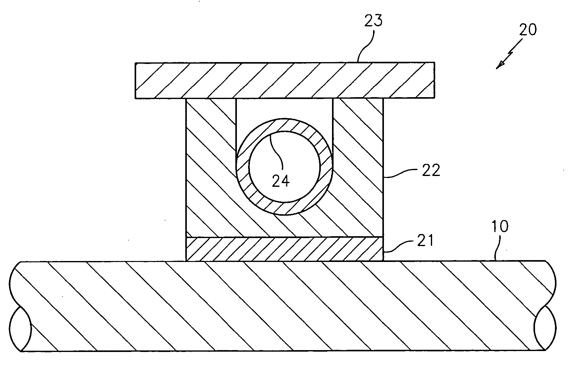
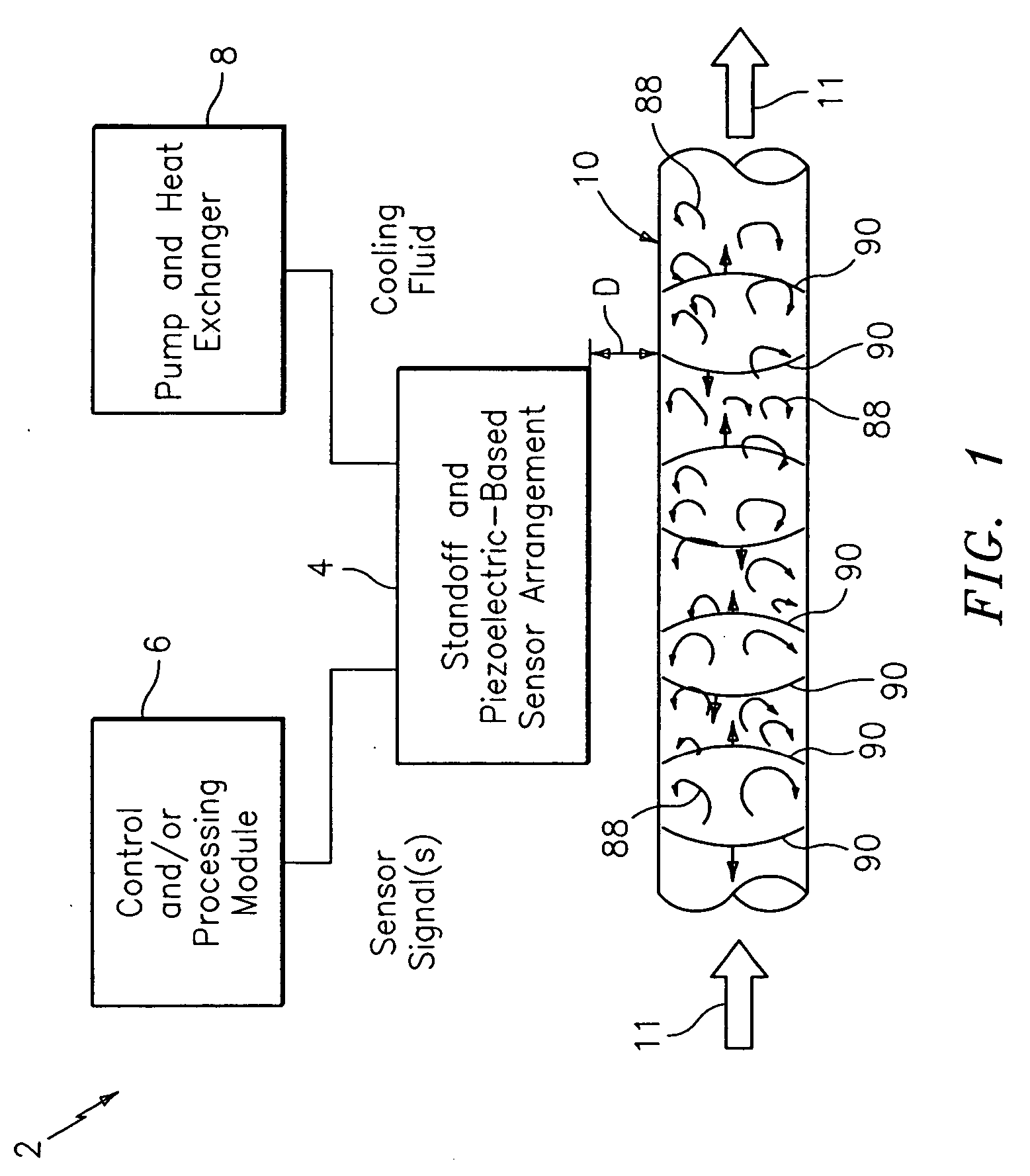
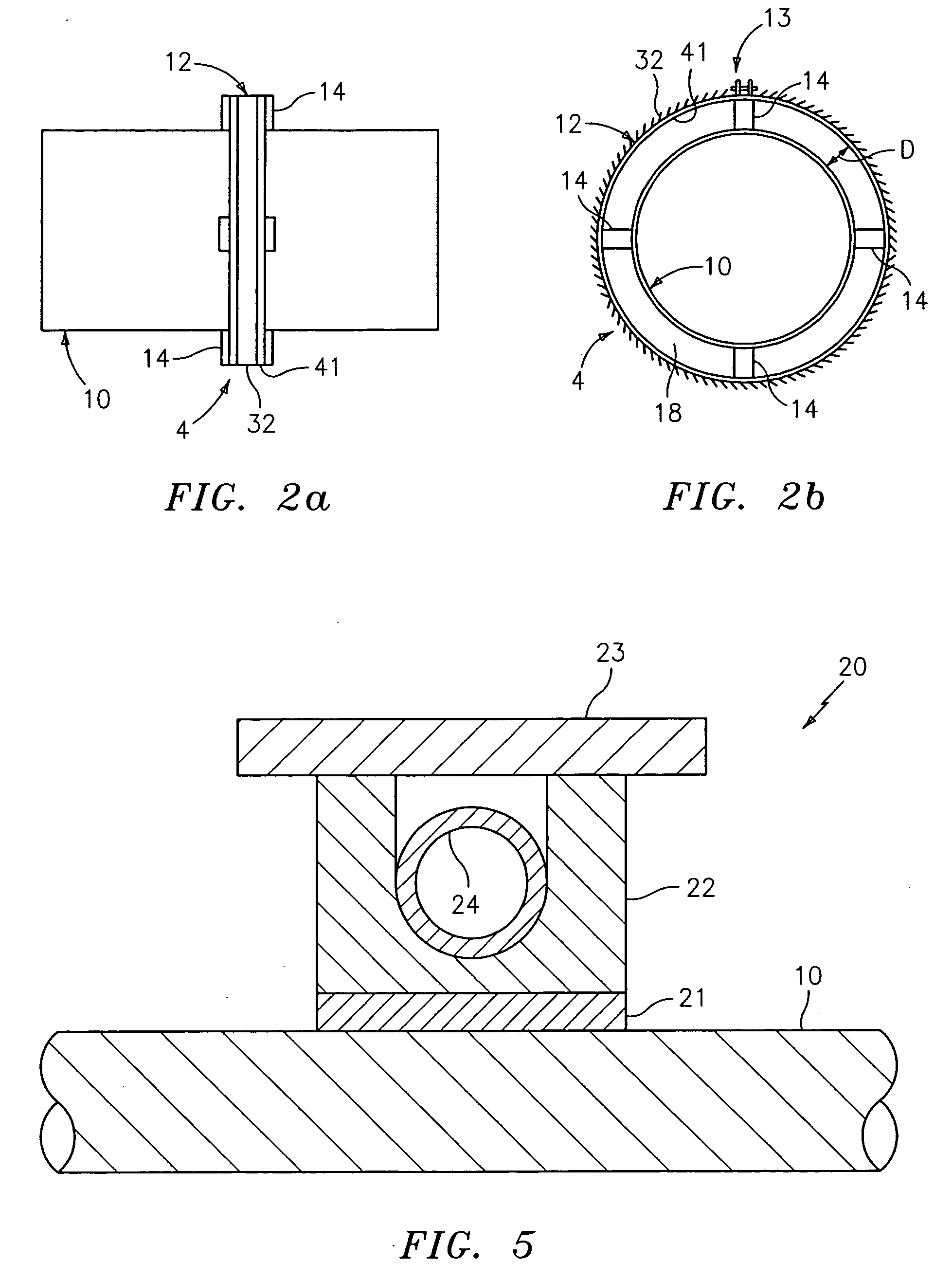
FIG. 1 shows a diagram of a system generally indicated as 2 according to the present invention, including a standoff and piezoelectric-based sensor arrangement 4, a control and / or processing module 6 and a pump and heat exchanger 8. The standoff and piezoelectric-based sensor arrangement 4 is arranged in relation to a pipe 10 and includes one or more sensors made of piezoelectric material, such as polyvinylidene fluoride (“PVDF”), that are arranged on one or more standoffs, which may be actively cooled, consistent with that described herein. The pipe 10 carries a process flow of a fluid or medium 11 that can reach very hot temperatures, such as steam.

Although the scope of the invention is not intended to be limited to the type or kind of fluid or medium 11 flowing in the pipe 10 per se, it is specifically designed to measure a parameter of the fluid or medium at very high temperatures, such as steam, using a piezoelectric-based sensor at temperatures substantially exceeding 125° C....


PUM


Abstract

A method, apparatus and system are provided to measure the process flow of a fluid or medium traveling in a pipe. The system and apparatus feature a standoff and piezoelectric-based sensor arrangement having a plurality of standoffs arranged on a pipe and a plurality of sensor bands, each arranged on a respective plurality of standoffs, each having at least one sensor made of piezoelectric material arranged thereon to detect unsteady pressure disturbances in the process flow in the pipe which in turn can be converted to the velocity of and/or speed of sound propagating within the pipe, and a cooling tube arranged in relation to the plurality of standoffs for actively cooling the sensor band; and further comprise a processing module for converting one or more sensor signals into a measurement containing information about the flow of the fluid or medium traveling in the pipe, as well as a pump and heat exchanger for processing the cooling fluid flowing through the cooling tube. The processing includes maintaining the cooling fluid at a desired operating temperature.

Description

BACKGROUND OF THE INVENTION 1. Technical Field The present invention relates to a system for measuring dynamic, unsteady pressures within a fluid or medium, including a fluid or medium having an extremely high temperature such as steam, flowing inside a pipe and using it to determine a parameter (e.g., flow velocity and / or speed of sound) of the fluid or medium; and more particularly to a system for measuring the same using a piezoelectric-based sensor device or the like. 2. Description of Related Art Techniques are known that enable flow and fluid parameter measurements which utilize an array of strain-based sensors, clamped onto the outside of a process piping. Depending on the specifics of the application, it is often desirable to use a strain sensor design to measure the circumferentially averaged strain within a pipe. One method to achieve circumferentially averaged strain within a conduit utilizes strain sensitive piezoelectric strips or bands. Although the flow monitoring...

Claims


Application Information

Patent Timeline
IPC IPC(8): G01F1/7082G01F1/712G01F1/74
CPCG01F1/662G01F1/74G01F1/712G01F1/7082
Inventor GYSLING, DANIEL L.DAVIS, MICHAEL A.DUNPHY, JAMES R.CROTEAU, PAUL F.MARON, ROBERT J.
Owner EXPRO METERS
Why Eureka
Try Eureka