Passive, thermocycling column heat-exchanger system

a technology of heat exchanger and thermocycling column, which is applied in the direction of lighting and heating equipment, other heat production devices, and stationary conduit assemblies, etc., can solve the problem of same boiling point, and achieve the effect of facilitating the percolation of seawater

Inactive Publication Date: 2000-11-07
EDG
View PDF20 Cites 60 Cited by
  • Summary
  • Abstract
  • Description
  • Claims
  • Application Information

AI Technical Summary

Benefits of technology

Unlike the prior art, the present invention contemplates a system for cooling high pressure, hot fluids from deep hydrocarbon reserves offshore, generally comprising a vertical heat exchange column (formed of a bundle of tubes) enveloped by a caisson or the like in order to facilitate percolation of seawater, so as to create a thermosyphonic effect, wherein seawater is drawn into and up the caisson, engaging the heat exchanger containing the hot fluid, cooling same utilizing the abundant supply of cold water in the area.

Problems solved by technology

When hot fluid passes down through the tube bundle, the seawater within the shell becomes heated, causing same to boil as it rises to the top of the tube bundle.

Method used


Image

  • Passive, thermocycling column heat-exchanger system
  • Passive, thermocycling column heat-exchanger system
  • Passive, thermocycling column heat-exchanger system

Examples


Embodiment Construction

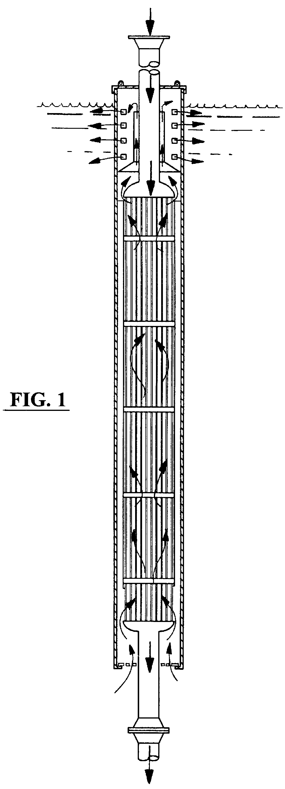
Referring to FIGS. 6-6C as well as FIGS. 4 and 5, the preferred embodiment of heat exchanger 1 of the present invention includes a tube bundle T (30' length in the exemplary embodiment) comprising a plurality of longitudinally aligned tubes, the tube bundle having first 101 and second 102 ends having first 9 and second 11 spherical or elliptical head caps affixed thereto, respectively, each head cap 9, 11 securely attached and closed off by tube sheets 14, 12 (individually shown as 14A in FIG. 6C) configured to sealingly engage and hold a plurality of heat exchanger tubes 10 forming the tube bundle, while allowing flow through the tube bundle, allowing flow from a supply line (3" diameter in the exemplary embodiment).

The tube bundle is fitted inside of a thin wall shell 4, formed with a conical section 15 at the top that is flared to fit the inside diameter of a caisson 2. The shell is cut at the lower end 16 a distance of about, for example, 6" from the bottom tube sheet. A bottom ...


PUM


Abstract

A heat exchanger system suitable for facilitating the economical cooling of hot fluids in the vicinity of a body of water. The preferred embodiment of the present invention contemplates a vertical, or combination vertical and horizontal thermosyphonic, passive, heat exchanger column situated in a body of water and enveloped by a caisson or the like, and configured to facilitate, through percolation, enhanced circulation of seawater therethrough and effecting significant cooling of a hot, hydrocarbon well stream, or other hot fluid in the vicinity of a body of water. A vertically situated bundle of tubes forms the heat exchanger, which may include a system of staggered baffles to direct the flow of cooling seawater to effect even temperature distribution throughout the tube bundle. The present system further teaches a system for cooling high pressure, hot fluids as may be found in a deep hydrocarbon reserve offshore, utilizing a the vertical heat exchange column of the present invention. Upon passing through the system, a gaseous fluid stream, significantly cooled, should experience a commensurate pressure reduction and allow the use of conventional pipeline materials. The present system dispenses with the necessity of providing expensive, pro-active cooling, generally expending significant fuel, or the necessity of constructing an expensive, high pressure, non-corrosive pipeline of, for example, titanium or the like.

Description

The present invention relates to heat exchangers, and in particular to a heat exchanger system suitable for facilitating the economical cooling of hot fluids, particularly high pressure gasses, in the vicinity of a body of water. The preferred embodiment of the present invention contemplates a vertical, or combination vertical and horizontal thermosyphonic, passive, heat exchanger column situated in a body of water and enveloped by a caisson or the like, configured to facilitate percolation and circulation of fresh water or seawater therethrough and effecting significant cooling of a hot, hydrocarbon, well stream of gas or other hot fluid. A vertically situated bundle of tubes forms the heat exchanger, which may include a system of baffles to direct the flow of cooling seawater, so as to provide more efficient heat transfer throughout the tube bundles.The system of the present invention further teaches a system for cooling high pressure, hot fluids such as natural gas or the like as...

Claims


Application Information

Patent Timeline
Patent Type & Authority Patents(United States)
IPC IPC(8): F28F9/22F28D1/02
CPCF28D1/0213F28F9/22F28D1/022F28D2021/0075
Inventor PAULSEN, DWIGHT C.BARNETT, LEON G.MOREAU, TIMOTHY J.
Owner EDG
Why Eureka
Try Eureka