
Scooter with folding and steering direction rod

A technology of steering direction and steering rod, which is applied to foldable bicycles, steering mechanisms, motor vehicles, etc. It can solve the problems of weakening the structural strength of steering rods, increasing the difficulty of vehicle assembly, and reducing productivity, so as to improve the convenience of storage and carrying High performance, easy adjustment, shortened folding length

Inactive Publication Date: 2016-10-19
CRAZYFIRE TECH CO LTD
View PDF7 Cites 6 Cited by
  • Summary
  • Abstract
  • Description
  • Claims
  • Application Information

AI Technical Summary

Problems solved by technology

[0002] The mobility vehicles involved in this article specifically refer to miniature mobility vehicles such as scooters, electric scooters, balance cars and mopeds. With the improvement of people's living standards, people pay more and more attention to leisure sports and pursue fashion. Leisure and stylish vehicles have folding functions for easy carrying and storage; the steering rod is a part that needs to be folded to significantly reduce the overall space occupancy of the car body, and since the steering rod is also used as a transmission element for direction control force, the existing technology The vehicle has a steering mechanism and a folding mechanism at different positions on the steering rod. This structure not only easily weakens the structural strength of the steering rod, but also generally causes insufficient folding. At the same time, it also increases the difficulty of vehicle assembly and reduces productivity. insufficient

Method used


Image

  • Scooter with folding and steering direction rod
  • Scooter with folding and steering direction rod
  • Scooter with folding and steering direction rod

Examples


Embodiment Construction

[0030] In order to make those skilled in the art better understand the technical solutions of the present invention, the present invention will be further described in detail below with reference to the accompanying drawings and the best embodiments.

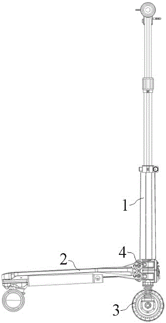
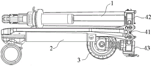
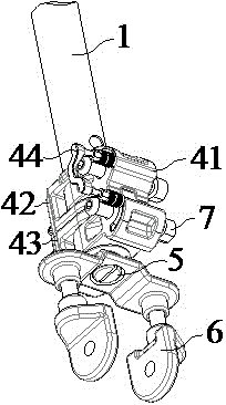
[0031] like Figure 1-4 As shown, a commuter vehicle with a foldable steering steering rod 1 of the present invention includes a pedal 2, a front wheel 3, a steering rod and a steering folding mechanism 4. The steering folding mechanism includes a hinge pin 7 connected to one end of the pedal. The hinge block 41, the upper folding block 42 fixedly connected with the lower end of the direction rod, the lower folding block 43 fixedly connected with the front wheel, and the folding lock 45 connecting the upper folding block and the lower folding block, the hinge block includes a hinge shaft (not shown in the figure). ), the upper hinge arm 411 and the lower hinge arm 412 respectively connected with the hinge shaft, the upper hinge ...


PUM


Abstract

The invention discloses a walking-replacing vehicle with a foldable steering rod, which includes a pedal, a front wheel, a steering rod and a steering and folding mechanism. The steering and folding mechanism includes a hinge block, an upper folding block, a lower folding block and a folding lock. The hinge block includes a hinge Shaft, upper hinge arm and lower hinge arm, the upper hinge arm and the lower hinge arm are respectively provided with pin holes and steering shaft holes; the upper folding block is provided with the first fixing hole for fixing the direction rod, the direction rod and the upper hinge arm bearing connection, the lower folding block has the same structure as the upper folding block, and the upper folding block and the lower folding block are provided with a fitting structure. The steering and folding mechanism of the mobility vehicle not only realizes the connection between the steering rod, the pedal and the steering main rod, but also realizes the dual functions of steering and folding. It has a simple structure, high production and assembly efficiency, reliable steering force transmission, and will not weaken the structural strength of the steering rod. , high reliability in use, and the overall shape and structure of the steering rod is beautiful, the volume of the car body is greatly reduced after folding, and it is easy to store and carry, which meets the fashion needs of new humans.

Description

technical field [0001] The invention relates to the technical field of mobility vehicles, in particular to a mobility vehicle with a foldable steering direction rod. Background technique [0002] The mobility vehicles involved in this article specifically refer to miniature mobility vehicles such as scooters, electric scooters, balance bikes and mopeds. With the improvement of people's living standards, people pay more and more attention to leisure sports and pursue fashion. The leisure and fashionable scooter has a folding function for easy carrying and storage; the directional rod is a foldable component that can significantly reduce the overall space occupancy rate of the vehicle body. The steering mechanism and the folding mechanism are respectively set at different positions on the direction rod of the scooter. This structure not only easily weakens the structural strength of the direction rod, but also causes insufficient folding. At the same time, it also increases th...

Claims


Application Information

Patent Timeline
Patent Type & Authority Applications(China)
IPC IPC(8): B62K15/00B62K3/00B62K21/16
CPCB62K15/006B62K3/002B62K21/16
Inventor 张一眀
Owner CRAZYFIRE TECH CO LTD
Learn More