
Hard disk lamp signal control circuit

A technology for controlling circuits and hard disks, applied in hardware monitoring, etc., can solve problems such as errors, the second light-emitting diode does not light up and display, and achieve the effect of controlling flickering

Active Publication Date: 2016-10-19
KUNDA COMP TECHKUSN +1
View PDF3 Cites 6 Cited by
  • Summary
  • Abstract
  • Description
  • Claims
  • Application Information

AI Technical Summary

Problems solved by technology

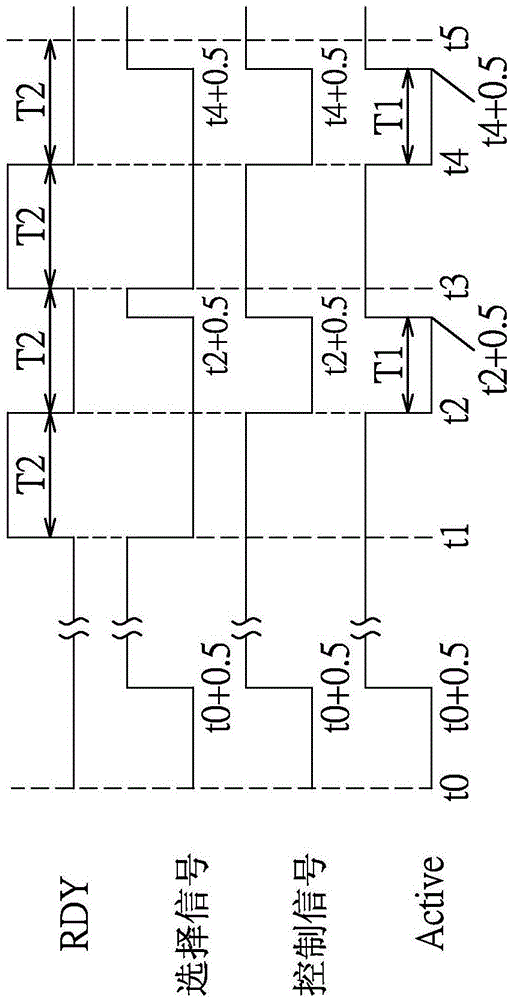
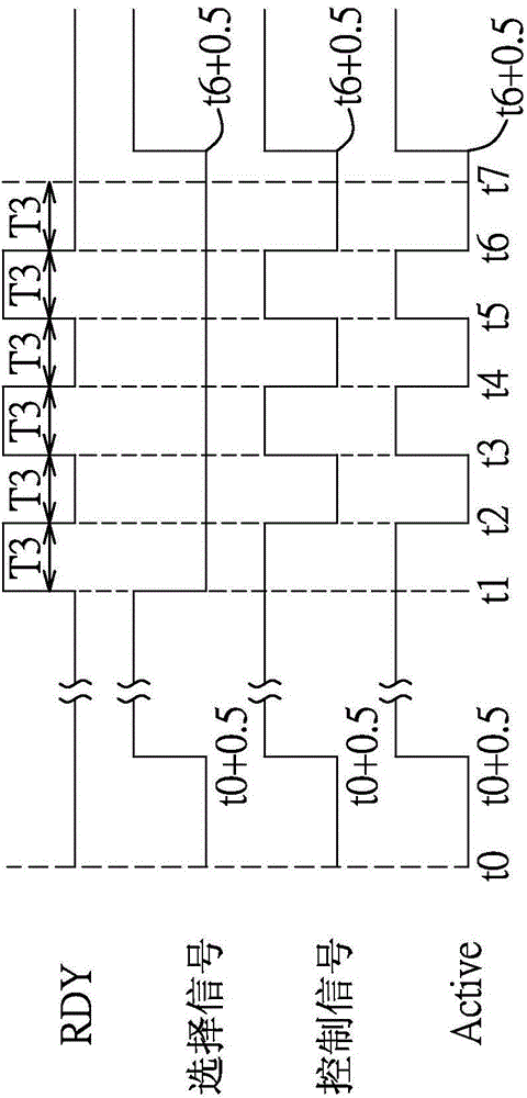
[0004] Therefore, the light-emitting diodes of the known computer system must adopt two designs for hard disks of different brands or different models. The second light-emitting diode is only illuminated when the logic is 1, and in the first state, the output status signal of the Seagate hard disk is logic 0, which causes the second light-emitting diode to not light and display an error

Method used


Image

  • Hard disk lamp signal control circuit
  • Hard disk lamp signal control circuit
  • Hard disk lamp signal control circuit

Examples


Embodiment Construction

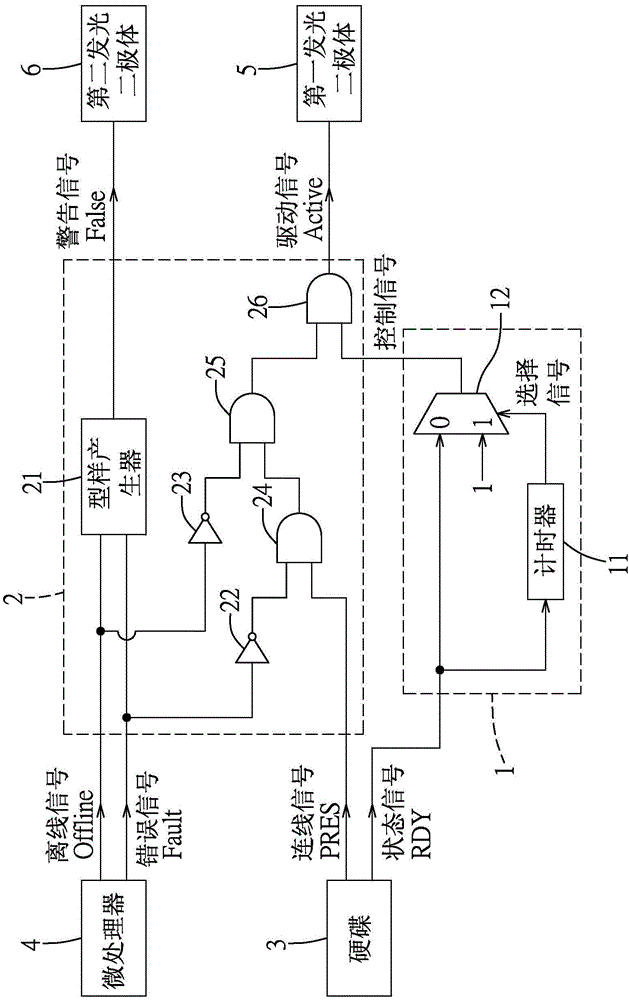
[0017] refer to figure 1 , the embodiment of the control circuit of the hard disk light signal of the present invention is applicable to a computer system comprising a hard disk 3, a microprocessor 4, a first light-emitting diode 5, and a second light-emitting diode 6, to receive information from the hard disk 3 A state signal RDY and a connection signal PRES, and receive an offline signal Offline and an error signal Fault from the microprocessor 4, and according to the state signal RDY, the connection signal PRES, the offline signal Offline, and The error signal Fault generates a driving signal Active and a warning signal False to respectively control the first LED 5 and the second LED 6 to emit light. When the first LED 5 emits light, it generates green light, and when the second LED 6 emits light, it generates red light.

[0018] In this embodiment, the status signal RDY and the connection signal PRES from the hard disk 3 conform to the Serial General Purpose Input / Output ...


PUM


Abstract

The invention provides a hard disk lamp signal control circuit suitable for receiving a status signal from a hard disk and generating a drive signal (according to the received signal) so as to control a LED to shine; the hard disk lamp signal control circuit comprises a first module and a second module; the first module comprises a timer and a multiplexer, wherein the timer receives the status signal and outputs a selection signal according to a logic value of the status signal; the multiplexer selects either the status signal or an indication logic reference voltage according to the selection signal, and outputs a control signal; the second module generates the drive signal according to the control signal; the hard disk lamp signal control circuit allows status signals from different hard disks and with different definitions to control the LED to shine, thus correctly indicating the hard disk status.

Description

technical field [0001] The invention relates to a control circuit, in particular to a control circuit for a hard disk light signal. Background technique [0002] A conventional computer system includes a microprocessor, a hard disk (HDD) electrically connected to the microprocessor, and a green light emitting diode (LED). The hard disk provides a state signal to control whether the light-emitting diode emits light and flickers, so as to indicate the operation state of the hard disk. The hard disk operates between a first state (Present State) and a second state (Active State). In the first state, the hard disk has been connected to the microprocessor, and the hard disk is idle (Idle) State, the state signal from the hard disk is logic 0 or logic 1, to control the LED to emit green light. In the second state, the hard disk has been connected with the microprocessor, and the hard disk is in the read or write state, and the state signal from the hard disk is jumping between l...

Claims


Application Information

Patent Timeline
Patent Type & Authority Applications(China)
IPC IPC(8): G06F11/32
Inventor 张哲维王季兴
Owner KUNDA COMP TECHKUSN
Learn More