A Method of Selecting Load Model in the Planning and Designing Stage of Power Network

A design stage, load model technology, applied in design optimization/simulation, calculation, data processing applications, etc.

Active Publication Date: 2020-06-30
STATE GRID CORP OF CHINA +3
View PDF6 Cites 0 Cited by
  • Summary
  • Abstract
  • Description
  • Claims
  • Application Information

AI Technical Summary

Problems solved by technology

[0008] The purpose of the present invention is to provide a method for selecting a load model in the planning and design stage of the power grid, so as to solve the problem of selecting a static model under what circumstances

Method used


Image

  • A Method of Selecting Load Model in the Planning and Designing Stage of Power Network
  • A Method of Selecting Load Model in the Planning and Designing Stage of Power Network
  • A Method of Selecting Load Model in the Planning and Designing Stage of Power Network

Examples


Embodiment 1

[0078] The method for selecting a load model in the grid planning and design stage of the present invention comprises the following steps:

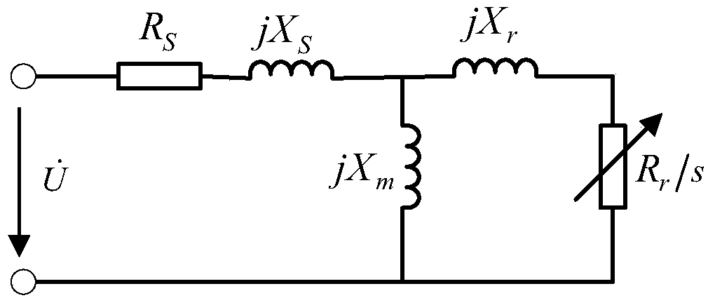
[0079] (1) Establish the load equation of the induction motor;

[0080]

[0081] (2) Determine the sensitive voltage u of the induction motor model 1 ;

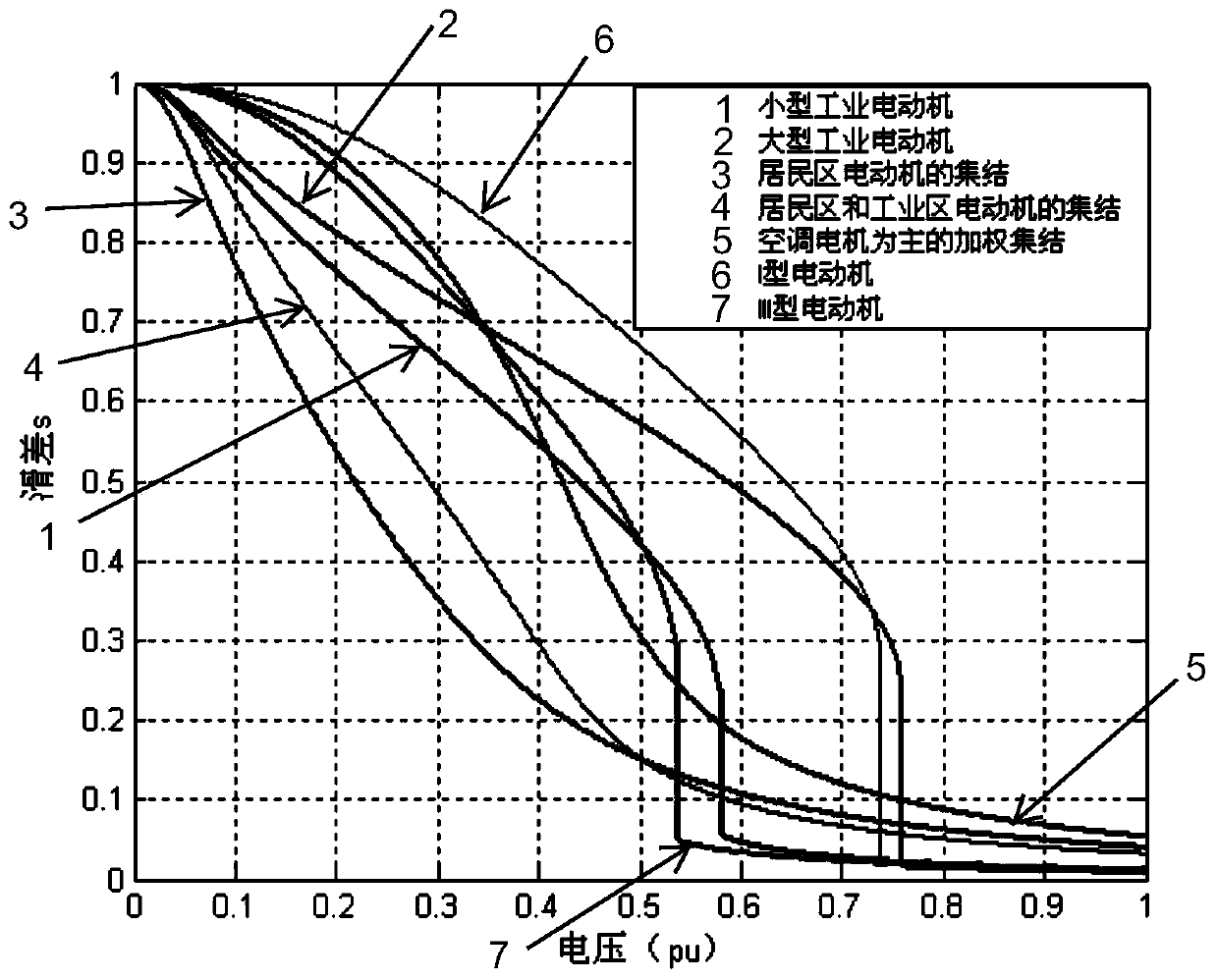
[0082] Such as Figure 3-11 As shown, when the power grid does not include large industrial motors and I-type motors, the sensitive voltage u 1 =0.58pu, preferably, u 1 =0.6pu; when the grid includes large industrial motors and I-type motors, the sensitive voltage u 1 =0.76pu, preferably, u 1 =0.8pu;

[0083] (3) Calculate the recovery voltage u of a component N-1 in the model after calibration 2 ;

[0084] (4) will restore the voltage u 2 and sensitive voltage u 1 for comparison, when u 2 greater than or equal to u 1 , the static load model is selected.

[0085] (5) will restore the voltage u 2 and sensitive voltage u 1 for comparison, when u 2 less than u 1 , check ...

Embodiment 2

[0087] Figure 11 It is a flow chart of a method for selecting a load model in the grid planning and design phase according to Embodiment 2 of the present invention.

[0088] The method for selecting a load model in the grid planning and design stage of the present invention comprises the following steps:

[0089] (1) Establish a grid model, including n electrical components in the grid model;

[0090] (2) N-1 checking is carried out to n electrical components in the grid model; wherein,

[0091] When a component is checked by N-1 and the recovery voltage is above 0.8pu, the static load model is selected.

Embodiment 3

[0093] A method for selecting a load model in the grid planning and design stage, characterized in that the method includes the following steps:

[0094] (1) Establish a grid model, including n electrical components in the grid model;

[0095] (2) Classify the motor and establish the load equation of the motor;

[0096]

[0097] In the formula, the first term is the constant impedance characteristic, and the second term is the constant current characteristic.

[0098] (4) Make the load characteristic curve of each type of motor;

[0099] (5) Determine the sensitive voltage of each type of motor according to step (4);

[0100] (6) Perform N-1 check on n electrical components in the grid model and record their recovery voltage u 2 ;in

[0101] When type I or large industrial motors are included in the grid model, when the recovery voltage u 2 When it is greater than or equal to 0.76, the static load model is selected, and when u 2 When less than 0.76, select the dynamic...


PUM


Abstract

The invention discloses a power grid planning and design phase load model selecting method; the power grid comprises an induction motor; the method comprises the following steps: 1, building an induction motor load equation; 2, determining the sensitive voltage u1 of an induction motor model; 3, calculating corrected recovery voltage u2 of an element N-1 in the model; 4, comparing the recovery voltage u2 with the sensitive voltage u1, and selecting a static state load model when u2 >= u1. The novel method can determine conditions under which the static state model can be selected in the power grid planning and design phase.

Description

technical field [0001] The invention relates to the field of thermal power generation, in particular to a method of how to select a load model in the planning and design stage of a power grid. Background technique [0002] In the power system analysis, it is determined based on the actual system test, or based on the capacity and utilization rate of the electrical equipment installed by the user, as well as the typical characteristics of similar electrical equipment, which is called a load model. Since the load varies greatly with day and night, working day, season, year, etc., and its composition is changeable, the determination of the load model and its parameters is a difficult problem in system analysis. [0003] As early as the 1930s, the importance of a reasonable load model for power system stability analysis was proposed, and the research on the load model began from then on. However, at that time, the stability problem was often regarded as a problem between genera...

Claims


Application Information

Patent Timeline
Patent Type & Authority Patents(China)
IPC IPC(8): G06F30/20G06Q50/06
Inventor 曹敏敏谢珍建储真荣史大军虞瑄窦飞王海潜张文嘉李琥
Owner STATE GRID CORP OF CHINA
Why Eureka
Try Eureka