Rotary display rack
A technology of display racks and turntables, which is applied to display hangers, display shelves, display tables, etc., can solve the problems of difficult access and poor display effect, and achieve the effect of convenient access
- Summary
- Abstract
- Description
- Claims
- Application Information
AI Technical Summary
Problems solved by technology
Method used
Image
Examples
Embodiment 1
[0041] This embodiment is used to illustrate a preferred structure of the support frame disclosed in the present invention.
[0042] like Figure 5 and Figure 6 As shown, the support frame includes a support rod 28, a first mounting seat 27, an outer frame 24, a drum 25 and a bracket 26, the turntable 1 is arranged in the drum 25, and the outer frame 24 is a circle shape, the number of outer ring frames 24 is 2, and the outer ring frames 24 are arranged at both ends of the inner wall of the drum 25, so as to fix and support the shape of the drum 25, and the bracket 26 is arranged at the bottom of the drum 25 , and contact support with a quarter of the arc at the bottom of the drum 25, the first mount 27 is used to fix the fixed gear 6, the support rods 28 have multiple, and one end of the support rods 28 is connected to the outer ring frame 24, the other end extends toward the center of the outer ring frame 24 and is fixed on the first mount 27;
[0043] The center of grav...
Embodiment 2
[0045] This embodiment is used to illustrate a preferred structure of the support frame disclosed in the present invention.
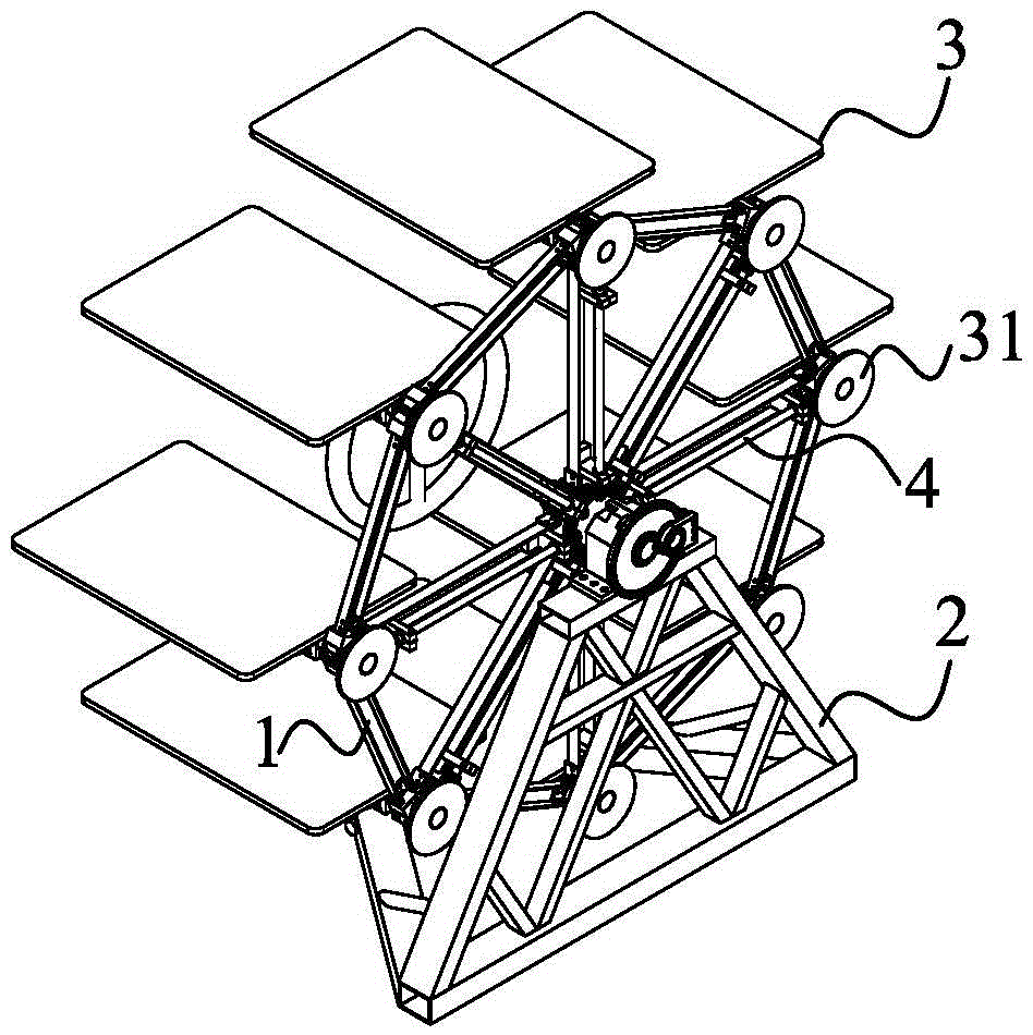
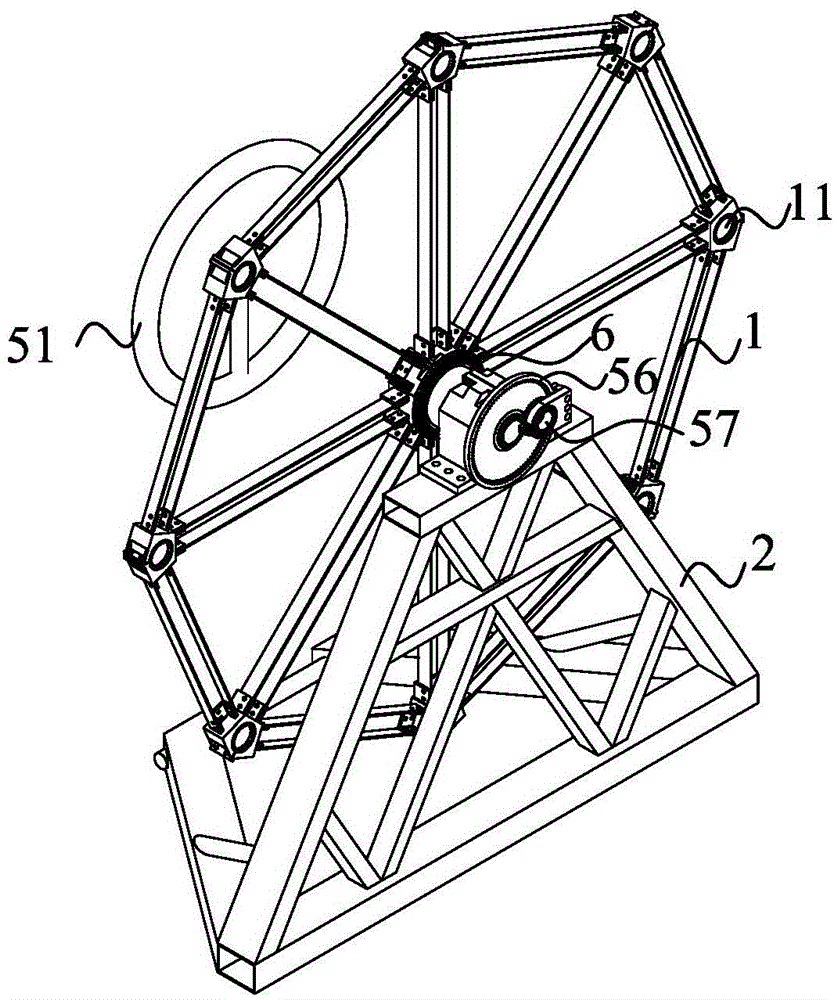
[0046] The support frame 2 is a skeleton structure, and the top of the skeleton structure is provided with a second mount 21 for fixing the fixed gear 6. The fixed gear 6 is provided with a fourth connecting shaft 59, and the fourth connecting shaft 59 Set on the central axis of the fixed gear 6, the fixed gear 6 is fixed on the second mount 21 through the fourth connecting shaft 59, and the axis position of the fourth connecting shaft 59 is provided with the first through hole 58 ; the supporting member 23 for connecting the planetary gear 57 is arranged on the side of the second mounting seat 21 .
[0047] Due to the large structural weight of the side where the turntable 1 is located on the rotating display stand, the force on both sides of the rotating display stand is uneven, and the side facing the turntable 1 bears a large load. A supporting bas...
Embodiment 3
[0050] This embodiment is used to illustrate the storage assembly and its installation structure disclosed in the present invention.
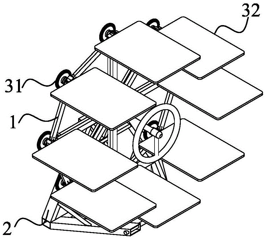
[0051] see Figure 7 and Figure 9 As shown, in this embodiment, the turntable 1 is provided with a third through hole 11, through the third through hole 11, the hinged installation between the storage assembly 3 and the turntable 1 is realized, and the storage table 32 and the driven gear 31 are located at both ends of the third through hole 11, and the storage assembly 3 also includes a third connecting shaft 33 connecting the storage table 32 and the driven gear 31, and the third connecting shaft 33 passes through the third through hole 11 and connects with The third through hole 11 is loosely fitted, and the storage table 32 and the driven gear 31 can realize synchronous rotation through the third connecting shaft 33 .
[0052] There are multiple storage assemblies 3, and a plurality of third through holes 11 are correspondingly arranged ...
PUM
 Abstract
Description
Claims
Application Information
 - R&D
- Intellectual Property
- Life Sciences
- Materials
- Tech Scout
- Unparalleled Data Quality
- Higher Quality Content
- 60% Fewer Hallucinations
Browse by: Latest US Patents, China's latest patents, Technical Efficacy Thesaurus, Application Domain, Technology Topic, Popular Technical Reports.
© 2025 PatSnap. All rights reserved.Legal|Privacy policy|Modern Slavery Act Transparency Statement|Sitemap|About US| Contact US: help@patsnap.com


