Cover safety structure of a pressure cooker lid

A pressure cooker and safety technology, applied in the direction of pressure cooker, etc., can solve the problems of incomplete movement, safety risk, handle rotation not in place, etc., to ensure normal use, improve safety, and avoid the effect of pressure rise

Active Publication Date: 2018-06-26
浙江福腾宝家居用品有限公司
View PDF8 Cites 0 Cited by
  • Summary
  • Abstract
  • Description
  • Claims
  • Application Information

AI Technical Summary

Problems solved by technology

[0004] In order to avoid excessive pressure in the pressure cooker, the current pressure cooker lid will adopt the structure of a stop rod to realize exhaust, or use a pressure valve to adjust the pressure in the pressure cooker, such as the clamp-type opening and closing lid disclosed in Chinese patent documents Pressure cooker [authorized announcement number CN2310519Y], the above-mentioned exhaust structure is based on the normal lid and body of the pressure cooker to ensure the safety of the pressure cooker, but at present, when people use the clamp type pressure cooker, there is a problem that the handle does not rotate properly. In place, the clamps are not fully moved to the position where the lid and the pot body are clamped. At this time, the connection strength between the lid and the pot body is low. When the pressure in the pressure cooker rises to a certain strength, the pressure Not enough pressure to push the stop lever or open the pressure valve, but the pressure may push the lid off the pot, posing a safety risk

Method used


Image

  • Cover safety structure of a pressure cooker lid
  • Cover safety structure of a pressure cooker lid
  • Cover safety structure of a pressure cooker lid

Examples


Embodiment Construction

[0024] The following are specific embodiments of the present invention and in conjunction with the accompanying drawings, the technical solutions of the present invention are further described, but the present invention is not limited to these embodiments.

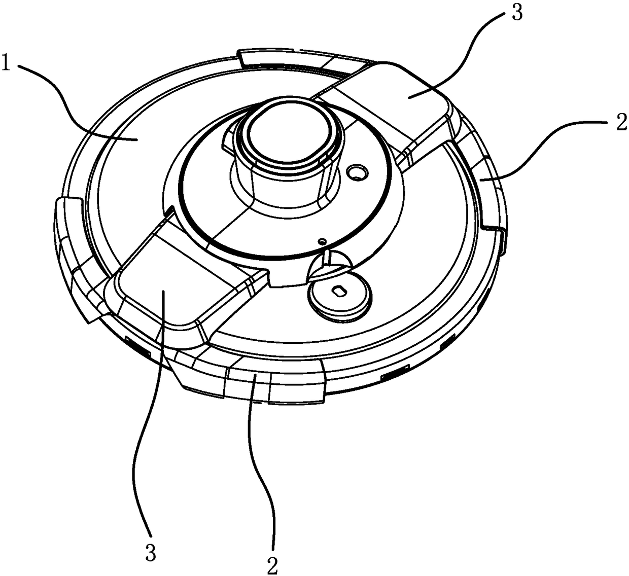
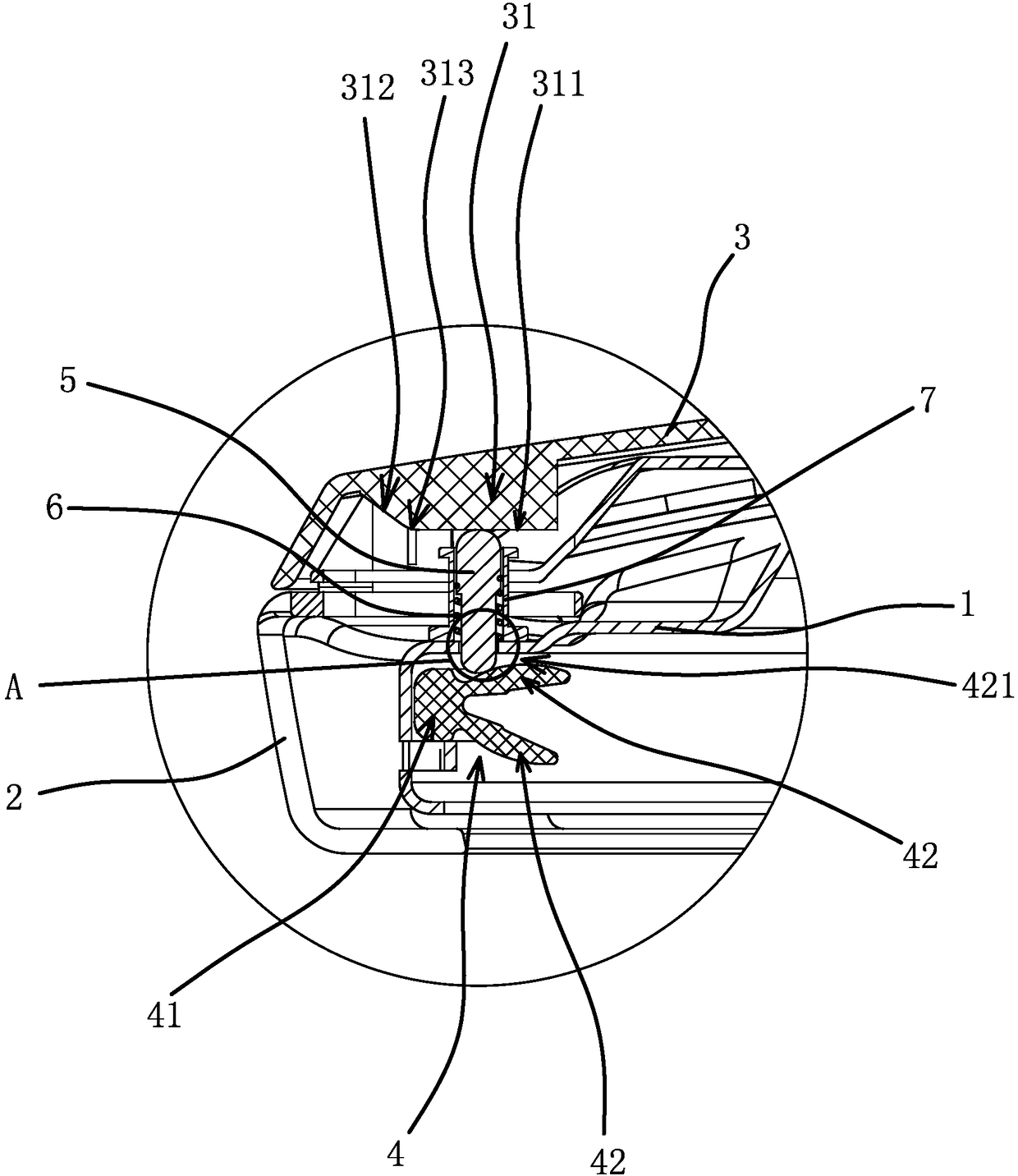
[0025] Such as figure 1 , figure 2 with Figure 4 As shown, the lid of the pressure cooker includes a cover body 1, a clamp 2 arranged on the edge of the cover body 1, and a cover sheet 3 that is fixedly connected with the clamp 2 and can drive the clamp 2 close to or away from the cover body 1. The cover body 1 covers the On the body of the pressure cooker, when the clamp 2 is at the position of the cover body 1, the cover body 1 can be taken off from the pot body at this time, and the pot cover is not completely closed on the pot body; by moving the center of the cover piece 3 and the cover body 1, the The clamp 2 is close to the cover body 1, and the clamp 2 will clamp the cover body 1 and the pot body. At this time,...


PUM


Abstract

The invention provides a pressure cooker cover closing safety structure and belongs to the technical field of cookers. The technical problem that an existing pressure cooker cover has the safety risk and the like is solved. A pressure cooker cover comprises a cover body, a clamp and a cover piece, wherein a sealing rubber ring is arranged on the inner side edge of the cover body. The cover closing safety structure comprises an ejection rod and an elastic part, a through hole is formed in the cover body, the ejection rod penetrates into the through hole, an air passing gap is reserved between the inner walls of the ejection rod and the through hole, the ejection rod is located between the sealing rubber ring and the cover piece, the elastic part makes the outer end of the ejection rod always abut against the cover piece, the inner side face of the cover piece is provided with an abutting plane and an oblique yield plane, the inner end of the ejection rod abuts against h the sealing rubber ring and a ventilation gap is formed between the sealing rubber ring and the inner side face of the cover body when the outer end of the ejection rod abuts against the abutting plane. The inner end of the ejection rod is separated from the sealing rubber ring when the outer end of the ejection rod abuts against the oblique yield plane. The pressure cooker cover closing safety structure has the advantages that the pressure in the pressure cooker can be prevented from rising when the pressure cooker cover is not completely closed on a cooker body.

Description

technical field [0001] The invention belongs to the technical field of cooking utensils, and relates to a pressure cooker, in particular to a lid closing safety structure of a pressure cooker lid. Background technique [0002] The pressure cooker ensures the airtightness of the pressure cooker during cooking, and realizes the increase of the pressure inside the pressure cooker, so as to achieve the purpose of heating the cooked food to above 100°C. Meal time saves energy. [0003] With the advancement of technology, there are more and more types of pressure cookers. According to the connection mode of the pot cover and the pot body, one of them is a clamp-type pressure cooker, such as a clamp with driving and self-locking structure disclosed in Chinese patent documents. Clamp type pressure cooker [Authorization Notice CN204192340U], the lid of this type of pressure cooker is provided with a clamp assembly, the clamp assembly includes a clamp, a cover piece and a handle, the...

Claims


Application Information

Patent Timeline
Patent Type & Authority Patents(China)
IPC IPC(8): A47J27/09
CPCA47J27/09
Inventor 郑祖福
Owner 浙江福腾宝家居用品有限公司
Why Eureka
Try Eureka