Hemostatic clip packaging box

A technology of hemostatic clips and packaging boxes, which is applied in the fields of wound clips, medical science, surgery, etc. It can solve the problems of affecting the operation effect and insufficient clamping force of the hemostatic clip, so as to improve the operation effect, prevent bleeding, and reduce the time.

Inactive Publication Date: 2016-10-26
CHENGDU IDING IND PROD DESIGN
View PDF5 Cites 10 Cited by
  • Summary
  • Abstract
  • Description
  • Claims
  • Application Information

AI Technical Summary

Problems solved by technology

At that time, the existing surgical clip appliers were mainly divided into single-shot and multi-shot. Among them, the single-shot type needed to be reinstalled with a new hemostatic clip after each hemostatic clip was applied, while the multi-shot type needed to be reinstalled after each hem

Method used


Image

  • Hemostatic clip packaging box
  • Hemostatic clip packaging box
  • Hemostatic clip packaging box

Examples


specific Embodiment 1

[0094] Specific embodiment 1: This embodiment discloses a hemostatic clip applier and a hemostatic clip packaging box;

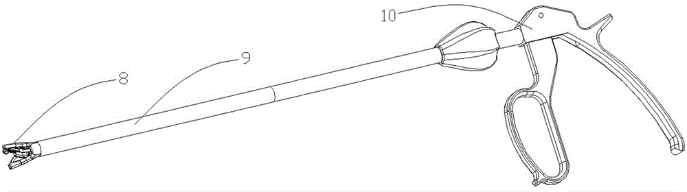
[0095] The hemostatic clip applier disclosed in this embodiment includes a pincer head 8, a pincer tube 9 connected to the pincer head, and a power device connected to the pincer tube 9;

[0096] The pincer tube 9 contains the clip 3, the push splint device, the right side plate 91 and the casing sleeve on the clip 3, the push splint device, and the right side plate 91;

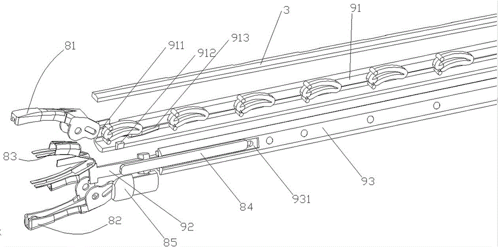
[0097] The magazine clip 3, the push splint device and the right side plate 9 enclose a passage for the advancement of the hemostatic clip;

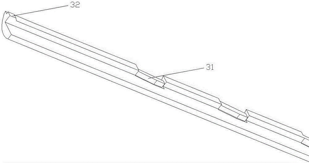
[0098] The magazine clip 3 is provided with a positioning groove;

[0099] The push splint device is provided with a push device to push the hemostatic clip forward;

[0100] The power plant 10 includes a tailpipe 106;

[0101] The pincer head 8 of the clip applier disclosed in this embodiment includes an upper jaw 81, a lower jaw 82, an elastic cl...

specific Embodiment 2

[0130] Specific embodiment 2: this embodiment has carried out further improvement to embodiment 1, and described improved parts and improved points are as follows:

[0131] Magazine 3 and right cover 2: as Figure 28 As shown, compared with the clip 3 in Embodiment 1, a limiting boss 33 is added at the output end, and at the same time, the output port of the guide groove c25 is provided with a concave platform 26 that cooperates with the limiting boss 33, so that the clip can Balanced in the box. The design of the position-limiting boss 33 ultimately enables the clip to better limit the position of the hemostatic clip on the clip and release it more accurately when the clip is loaded into the clip applier.

[0132] Right side plate (91): The top of the right side plate close to the end of the forceps head is provided with a limiting platform 919 for limiting the hemostatic clip. When the clip applier releases the hemostatic clip, the limiting platform can more accurately Lim...


PUM


Abstract

The invention discloses a hemostatic clip packaging box, and belongs to the field of medical articles, aiming at solving the problem of an existing packaging box that the performance of a hemostatic clip is easy to decline. The packaging box comprises a box body which is formed by fastening a left cover plate and a right cover plate, wherein the box body is provided with a conveying passage in a length direction of the box body and a compression passage which is perpendicular to the conveying passage; a cartridge holder is arranged in the conveying passage; two ends of the conveying passage are an output end and an input end; a sliding cover, by which the hemostatic clip is compressed to a compressed state from stretching state, is matched with the compression passage in a sliding mode; a pushing-pulling device is matched with the cartridge holder; and the cartridge holder, under force exerted by the pushing-pulling device, is moved from the output end.

Description

technical field [0001] The invention relates to the field of surgical medical machinery, in particular to a packing box for a hemostatic clip. Background technique [0002] Hemostatic clips are an important part of modern medical operations, especially minimally invasive operations. The existing hemostatic clips are mainly divided into titanium alloy hemostatic clips and polymer material hemostatic clips. Among them, titanium alloy hemostatic clips cannot be absorbed by the human body. After a period of time, it needs to be manually removed, and has a certain impact on MRI, while the hemostatic clip made of polymer materials can be absorbed by the human body without affecting MRI, and it has a wide application prospect in medical operations. At that time, the existing surgical clip appliers were mainly divided into single-shot and multi-shot. Among them, the single-shot type needed to be reinstalled with a new hemostatic clip after each hemostatic clip was applied, while the...

Claims


Application Information

Patent Timeline
IPC IPC(8): A61B50/30A61B17/128A61B17/122
CPCA61B17/1222A61B17/1227A61B17/1285
Inventor 张文俊
Owner CHENGDU IDING IND PROD DESIGN
Why Eureka
Try Eureka