Leg massaging robot for medical nursing

A robot and leg technology, applied in the field of leg massage robots, can solve the problems of small application range, non-adjustable massage angle, small massage range, etc., and achieve the effect of large application range, adjustable massage width, and large massage range

Inactive Publication Date: 2016-10-26
袁青
View PDF5 Cites 9 Cited by
  • Summary
  • Abstract
  • Description
  • Claims
  • Application Information

AI Technical Summary

Problems solved by technology

[0004] In order to solve the above problems, the present invention provides a leg massage robot for medical care, which can solve the problem of non-adjustable leg massage height, manual adjustment of massage position, small massage range, The massage angle is not adjustable, the massage width is not adjustable, the application range is small, the massage force is uneven, the massage effect is poor, the equipment shakes during the massage process, and the massage stability is poor. It can realize the automatic lifting massage function with stable legs. The massage height is adjustable, no need to manually adjust the massage position, the massage range is large, the massage angle is adjustable, the massage width is adjustable, the application range is large, the massage force is uniform, the massage effect is good, there is no shaking phenomenon and the massage stability is good, etc. Provides a new approach to leg massage

Method used


Image

  • Leg massaging robot for medical nursing
  • Leg massaging robot for medical nursing
  • Leg massaging robot for medical nursing

Examples


Embodiment Construction

[0024] In order to make the technical means, creative features, goals and effects achieved by the present invention easy to understand, the present invention will be further described below in conjunction with specific illustrations.

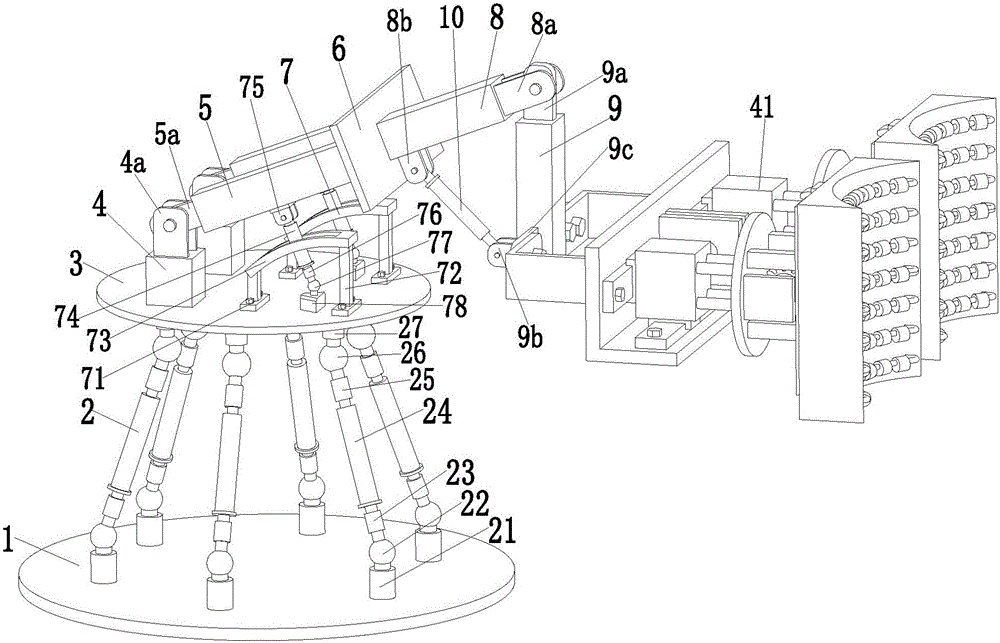
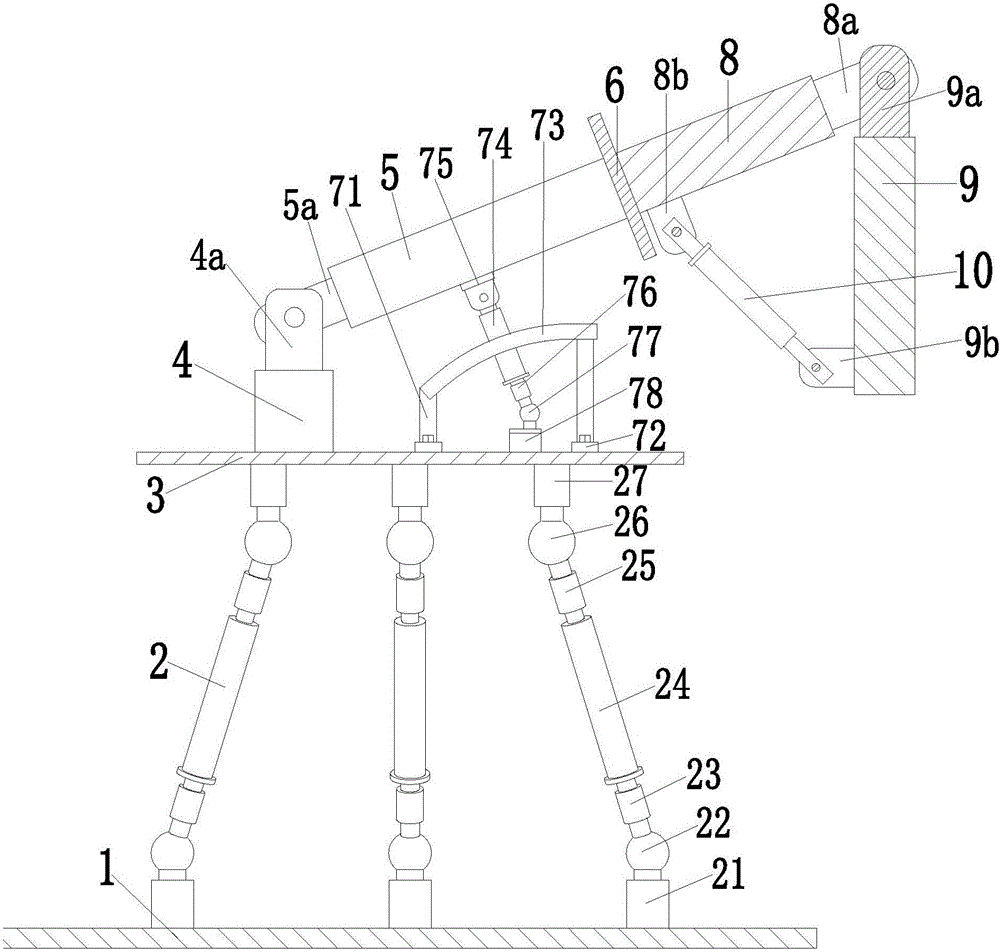
[0025] Such as Figure 1 to Figure 5 As shown, a leg massage robot for medical care includes a lower platform 1, the upper end surface of the lower platform 1 is uniformly installed with six parallel branch chains 2 along the axis direction, and the upper ends of the six parallel branch chains 2 are evenly Installed on the upper platform 3; the parallel branch chain 2 includes a hollow lower threaded shaft 21 whose lower end is welded on the lower platform 1, and a No. 1 spherical hinge 22 is installed on the hollow lower threaded shaft 21 through threaded connection. A No. 1 sleeve 23 is installed on the upper end through a threaded connection, and a No. 1 hydraulic cylinder 24 is installed on the upper end of the No. 1 sleeve 23 through a thre...


PUM


Abstract

The invention relates to a leg massaging robot for medical nursing. The leg massaging robot comprises a lower platform, wherein six parallel branched chains are uniformly arranged on the upper end face of the lower platform in an axial direction, and the upper ends of the six parallel branched chains are uniformly arranged on an upper platform; two cushion blocks are symmetrically arranged on the left side of the upper end face of the upper platform; two pairs of No.1 fixing lugs are separately arranged on the two cushion blocks; two No.2 fixing lugs are arranged on the two pairs of No.1 fixing lugs by virtue of pin shafts; the two No.2 fixing lugs are arranged at the tail ends of No.1 regulating rods; a regulating plate is welded at the top ends of the two No.1 regulating rods, and two angle regulating branched chains are connected between the lower end faces of the two No.1 regulating rods and the upper platform; and by virtue of the angle regulating branched chains, the inclination angles of the No.1 regulating rods, relative to the upper platform, are regulated. The leg massaging robot disclosed by the invention can achieve a stable automatic lifting massaging function on legs; therefore, a new way is provided for massaging the legs.

Description

technical field [0001] The invention relates to the field of medical equipment, in particular to a leg massage robot for medical care. Background technique [0002] With the continuous advancement of science and technology, people's requirements for material and cultural life are getting higher and higher. How to maintain health has become a matter of great concern in people's daily life. People are busy all day, and the human body is in a busy and tense state from head to toe. If you don’t get relaxation in time, it will cause damage to various tissues of the human body if it goes on for a long time. In severe cases, it will affect the function of the body, and even cause diseases, which is not conducive to the health care of the human body. . The legs are one of the parts with higher movement frequency and greater stress, so it is very important to massage and relax the legs, but it is often overlooked. [0003] Existing leg massager massage methods generally include one...

Claims


Application Information

Patent Timeline
Patent Type & Authority Applications(China)
IPC IPC(8): A61H7/00
CPCA61H7/00A61H7/007A61H2201/1238A61H2201/149A61H2201/164A61H2201/1669A61H2205/10
Inventor 沈永根
Owner 袁青
Why Eureka
Try Eureka