Automatic cover tarpaulin device for carriage and application method
A tarpaulin and car box technology, applied in the field of car box automatic cover tarpaulin devices, can solve the problems of poor covering, loss of scattered objects, economic losses, etc., and achieve the effect of smooth and stable movement of the mechanism and meeting the needs of work.
- Summary
- Abstract
- Description
- Claims
- Application Information
AI Technical Summary
Problems solved by technology
Method used
Image
Examples
Embodiment 1
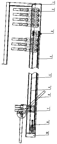
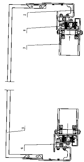
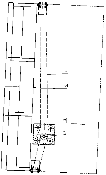
[0029]Embodiment 1. The present invention is composed of a remote controller, an intelligent controller, a motor, a double output shaft reducer, a reducer bracket, a tarpaulin protective cover 1, a single bearing pulley assembly 2, a wire rope support assembly 3, and a tarpaulin deployment wire rope 4, Tarpaulin retraction wire rope 5, thick wire rope track 6, double bearing pulley assembly 7, tail U-shaped frame automatic reset device 8, wire rope tightening device 9, guide rail support frame 10, tarpaulin U-shaped frame 11, wire rope pulley block assembly 12 The motor and the double output shaft reducer are installed together by bolts, while the reducer is installed on the reducer bracket, the reducer bracket is installed on the wire rope pulley block assembly 12, and fixed by bolts, the wire rope pulley block assembly 12 is welded on On the front part 13 of the car box body, and the wire rope support assembly 3 is also welded on the front part 13 of the car box body; one end...
Embodiment 2
[0030] Embodiment 2, the described wire rope pulley block assembly 12 is composed of a lower fixing plate 14, a bearing 15, a first positioning sleeve 16, a first pin shaft 17, two upper first pulleys 18, a second pulley 19, two lower First pulley 18, second pin shaft 20, second positioning sleeve 21, upper cover plate 22, third pin shaft 23, third positioning sleeve 24, first pin shaft 17, second pin shaft 20, third pin shaft The shaft 23 is welded on the lower fixed plate 14 respectively, and the second positioning sleeve 21 is installed on the second bearing pin 20; the upper two first pulleys 18 with the bearing 15, the second pulley 19 with the flat key and the bearing are housed. The next two first pulleys 18 of 15 are respectively installed on the first bearing pin 17, the second bearing pin 20, the third bearing pin 23, and then the first positioning sleeve 16, the second positioning sleeve 21, the third positioning sleeve 24 Be respectively installed on the first bear...
Embodiment 3
[0031] Embodiment 3, the described steel wire rope support assembly 3, it is made up of pin shaft fixing frame 25, nut 26, support positioning sleeve 27, support pulley 28, support pin 29, support bearing 30, and support bearing 30 is installed on support pulley 28, the support pulley 28 that support bearing 30 is housed is installed on support pin shaft 29 two ends respectively, and support positioning sleeve 27 is installed at both ends, then the whole is installed on the pin shaft fixed frame 25, and both sides pass through Nut 26 is tightened and fixed.
PUM
 Abstract
Description
Claims
Application Information
 - R&D
- Intellectual Property
- Life Sciences
- Materials
- Tech Scout
- Unparalleled Data Quality
- Higher Quality Content
- 60% Fewer Hallucinations
Browse by: Latest US Patents, China's latest patents, Technical Efficacy Thesaurus, Application Domain, Technology Topic, Popular Technical Reports.
© 2025 PatSnap. All rights reserved.Legal|Privacy policy|Modern Slavery Act Transparency Statement|Sitemap|About US| Contact US: help@patsnap.com


