A centrifugal automatic transmission
An automatic transmission and transmission technology, applied in chain/belt transmission, vehicle gearbox, transportation and packaging, etc., can solve problems such as troublesome operation and wrong gear position, and achieve simple components, long service life, The effect of high transmission efficiency
- Summary
- Abstract
- Description
- Claims
- Application Information
AI Technical Summary
Problems solved by technology
Method used
Image

Examples
Embodiment 1
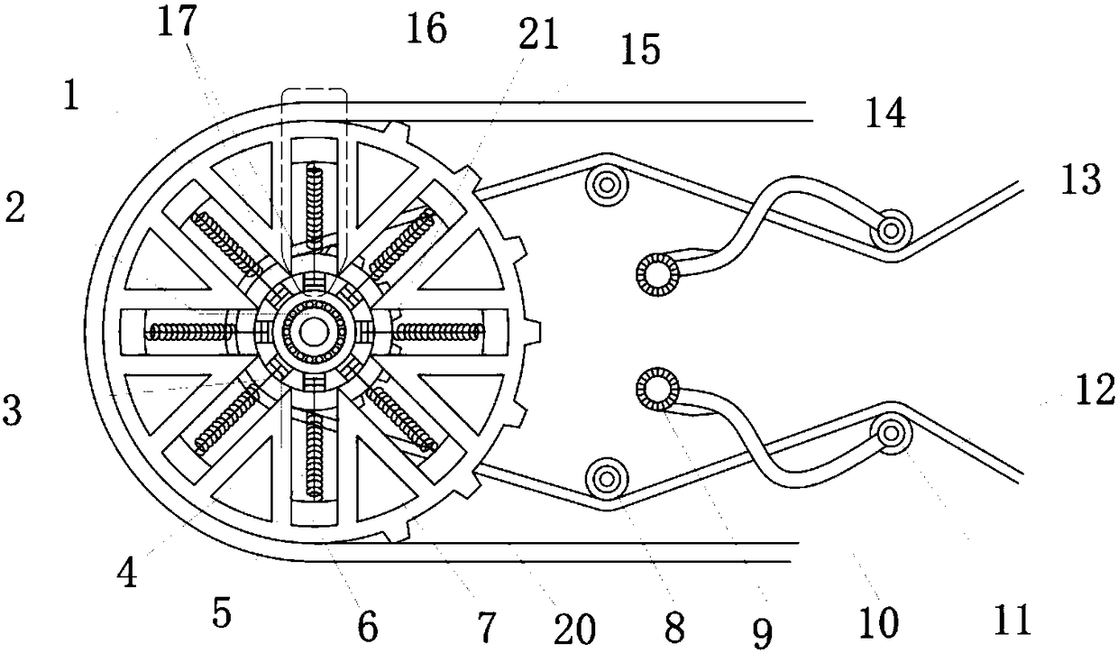
[0039] The technical solution described in the present invention is the first type of automatic transmission device. When the speed change slider unit 16 moves from the maximum speed difference state to the minimum speed difference state during use, the movement conditions between the various components are as follows:
[0040] When the first slide block 7 arrived at the minimum circumferential position, the second slide block 6 was at the maximum circumferential position, and now the speed change slider unit 16 was in the maximum speed difference state, that is, the linear velocity difference of the two slide blocks was the largest, and at this moment for the drive It is the most strenuous for the device, and the movable spacer wheel 11 is in the minimum position. In order to save effort, when the linear speed of the active chain 12 decreases, the speed of the slider wheel 17 also slows down, the centrifugal force difference of the sliders becomes smaller, the second slider 6 ...
Embodiment 2
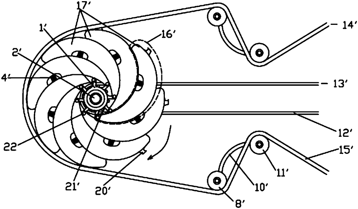
[0044] Such as image 3 Each of the variable-speed rotary vane units 16' on the rotary vane wheel 17' includes a rotary vane 23 that is rotatably connected to the central bearing 2' through a rotary joint 22. The outer side of the rotary vane 23 is provided with a spring buckle 2301, and the inner side There is a groove 2302, and the spring 5 connects the groove 2302 to the spring buckle 2301 of another blade 23, and the other end of the blade 23 corresponding to the end connected to the rotary joint 22 is provided with a buckle sprocket 20' , the outer edge of the fixed wheel 1' is provided with a drive chain sprocket 21', the drive chain 12' is interlocked with the drive chain sprocket 21' on the fixed wheel 1', and the driving device 13' passes through the drive chain 12 'Drive the fixed wheel 1' to rotate, and the rotating fixed wheel 1' takes the center bearing 2' as the center of the circle to drive the rotary vane wheel 17' to rotate through the rotary switch joint 22, ...
Embodiment 3
[0049] Propose further embodiment three on the basis of embodiment one, two, as Figure 5 Shown this embodiment and embodiment one, two differences are:
[0050] Such as Figure 5 As shown, the fixed wheel 1" in this embodiment is composed of the fixed wheel 1 of the first embodiment and the fixed wheel 1' of the second embodiment superimposed and fixed on the same axis, and the active chain 12" is linked with the slider 7". The driven chain 14 "is linked with the buckle sprocket 20" on the impeller 17 "; the fixed wheel 1 in the first embodiment is no longer linked with the driven chain 14 ", and the fixed wheel 1' is no longer linked with the driven chain 14 in the second embodiment. Active with 12" link.
[0051] Other similarities between this embodiment and Embodiment 2 will not be repeated here.
[0052] To sum up, the centrifugal automatic transmission device of the present invention, through the change of the centrifugal force on the variable-speed rotary vane unit ...
PUM
 Abstract
Description
Claims
Application Information
 - R&D
- Intellectual Property
- Life Sciences
- Materials
- Tech Scout
- Unparalleled Data Quality
- Higher Quality Content
- 60% Fewer Hallucinations
Browse by: Latest US Patents, China's latest patents, Technical Efficacy Thesaurus, Application Domain, Technology Topic, Popular Technical Reports.
© 2025 PatSnap. All rights reserved.Legal|Privacy policy|Modern Slavery Act Transparency Statement|Sitemap|About US| Contact US: help@patsnap.com