Electrical cabinet door lock with lock box

A technology for electrical cabinets and door locks, applied in building locks, non-mechanical drive-operated locks, buildings, etc., can solve the problems of inconvenient installation and use, low reliability, complex structure, etc., to achieve convenient operation and use, strong anti-theft performance, Reliable effect

Inactive Publication Date: 2016-10-26
ZHEJIANG ZHONGZHENG LOCK CO LTD
View PDF5 Cites 3 Cited by
  • Summary
  • Abstract
  • Description
  • Claims
  • Application Information

AI Technical Summary

Problems solved by technology

[0003] In order to overcome the common electromagnetic and mechanical dual control locksets in the prior art, which can only be used alone and cannot be matched with the electric cabinet door lock with a lock box, and at the same time, its structure is too complicated, its reliability is low, and its installation and use are relatively inconvenient. Problem, the present invention provides a lockset for an electrical cabinet door lock with a lock box. The electric cabinet door lock with a lock box has a compact structure, easy operation and use, strong anti-theft performance, and high reliability

Method used


Image

  • Electrical cabinet door lock with lock box
  • Electrical cabinet door lock with lock box
  • Electrical cabinet door lock with lock box

Examples


Embodiment Construction

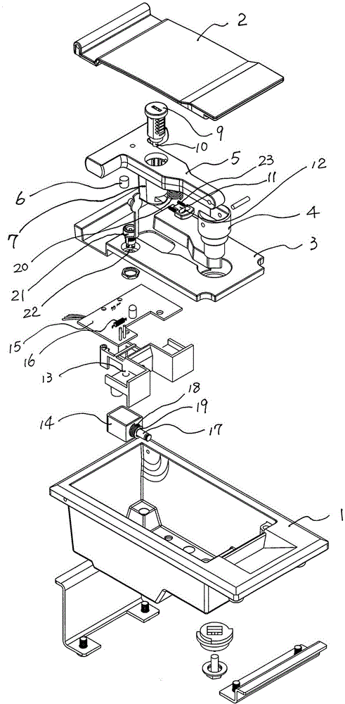
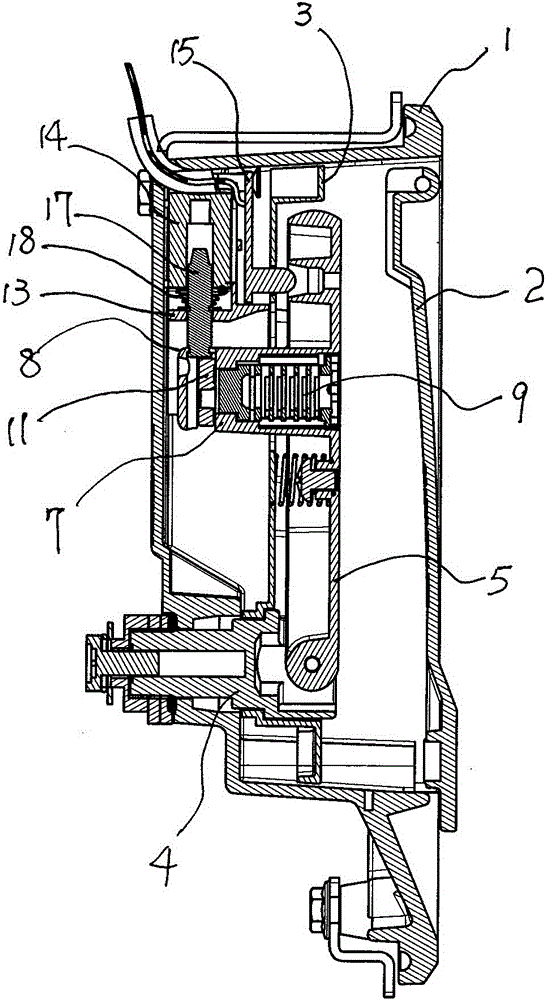
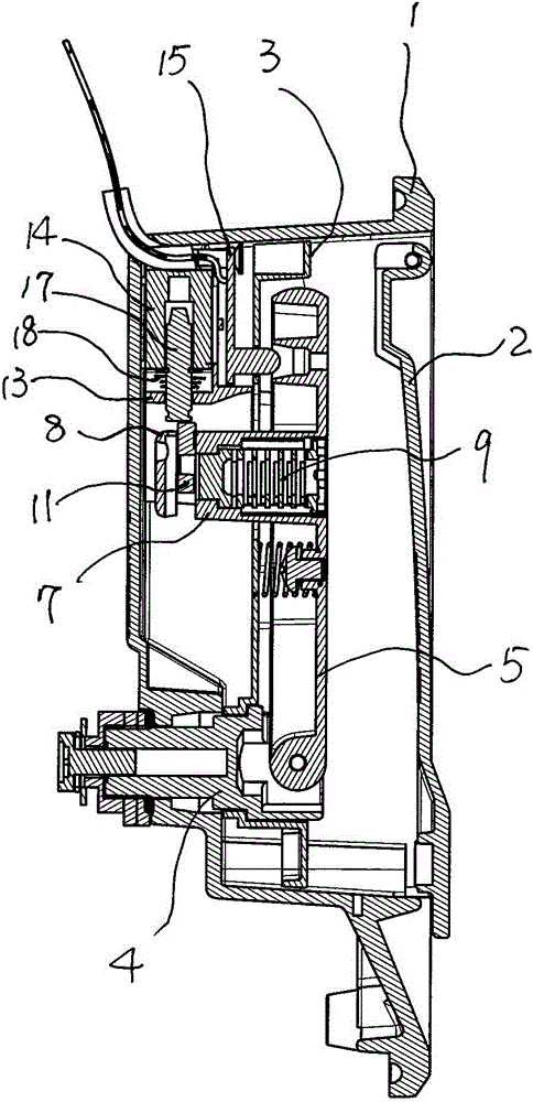
[0014] As shown in the figure, the present invention includes a lock box body 1 and a box cover 2 hinged on the lock box body 1, a bracket plate 3 is fixed inside the lock box body 1, and an unlocking shaft 4 is positioned and installed on the bracket plate 3, and the unlocking shaft 4 is connected The unlocking handle 5 is provided with a magnetic block 6 and a protruding locking part 7 on the unlocking handle 5. The locking part 7 passes through the bracket plate 3, and the corner of the lower end of the locking part 7 is formed as a pushing part 8, which is installed in the locking part 7. Lock core 9, the bottom of lock core 9 is eccentrically provided with driving lever 10, and driving lever 10 is connected with sliding locking piece 11 through long groove 12 on sliding locking piece 11, and one side of sliding locking piece 11 in locking part 7 is provided with the second The return spring 23, the second return spring 23 resets the sliding lock piece 11. Below the suppor...


PUM


Abstract

The invention relates to an electrical cabinet door lock with a lock box. The electrical cabinet door lock with the lock box comprises a lock box body and a box cover hinged to the lock box body. An unlocking rotation shaft is located and installed on a support plate in the lock box body. An unlocking handle is connected to the unlocking rotation shaft and provided with a magnetic block and a protruding locking portion. The locking portion penetrates the support plate, and the corner of the lower end of the locking portion forms a push and press portion. A lock cylinder is installed in the locking portion. A shift lever is eccentrically arranged at the bottom of the lock cylinder and connected with a sliding lock plate. A coil support is arranged below the support plate and located on one side of the locking portion. An electromagnetic coil and a circuit board which are electrically connected are fixed to the coil support. The circuit board is provided with a sensor matched with the magnetic block. A sliding lock pin is located and arranged in the electromagnetic coil in a sliding manner. The sliding lock pin is sleeved with a first reset spring. The first reset spring is located between the electromagnetic coil and a locating sheet fixed to the sliding lock pin in the radial direction in an abutting manner. One end of the sliding lock pin is matched with the sliding lock plate. The electrical cabinet door lock with the lock box has the beneficial effects of being compact in structure, convenient to operate and use, high in anti-theft performance and high in reliability.

Description

technical field [0001] The invention relates to an electrical cabinet door lock with a lock box. Background technique [0002] In order to improve the anti-theft performance of electric cabinet door locks, locks using electromagnetic and mechanical dual control have appeared in the prior art, but in actual use, the electromagnetic control and mechanical control of the above-mentioned locks can only be used alone and cannot be combined with lock boxes. The electrical cabinet door locks are matched, and at the same time, their structures are too complicated, their reliability is low, and their installation and use are also relatively inconvenient. Contents of the invention [0003] In order to overcome the common electromagnetic and mechanical dual control locksets in the prior art, which can only be used alone and cannot be matched with the electric cabinet door lock with a lock box, and at the same time, its structure is too complicated, its reliability is low, and its ins...

Claims


Application Information

Patent Timeline
Patent Type & Authority Applications(China)
IPC IPC(8): E05B65/52E05B47/06
CPCE05B65/52E05B47/0673
Inventor 陈成忠
Owner ZHEJIANG ZHONGZHENG LOCK CO LTD
Why Eureka
Try Eureka