
Unloading hydraulic system

A technology of hydraulic system and unloading valve, which is applied in the direction of fluid pressure actuators, servo motors, servo motor components, etc., and can solve problems such as large power loss

Active Publication Date: 2016-10-26
JIANGSU HENGLI HYDRAULIC TECH CO LTD
View PDF8 Cites 0 Cited by
  • Summary
  • Abstract
  • Description
  • Claims
  • Application Information

AI Technical Summary

Problems solved by technology

The power loss of the two systems is relatively large

Method used


Image

  • Unloading hydraulic system

Examples


Embodiment Construction

[0016] The following will clearly and completely describe the technical solutions in the embodiments of the present invention. Obviously, the described embodiments are only some of the embodiments of the present invention, rather than all the embodiments. Based on the embodiments of the present invention, all other embodiments obtained by persons of ordinary skill in the art without making creative efforts belong to the protection scope of the present invention.

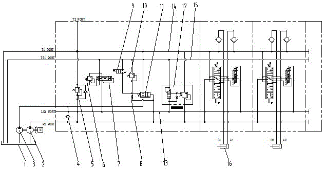
[0017] see figure 1 , an unloading hydraulic system, including a hydraulic oil tank 1, a first quantitative pump 2, a second quantitative pump 3, an unloading valve 11 and a two-stage unloading valve 12, the first quantitative pump 2 and the second quantitative pump 3 The inlet of the pump is connected to the hydraulic oil tank 1, the outlets of the first quantitative pump 2 and the second quantitative pump 3 are connected through a one-way valve 4, and the unloading valve 11 is connected to the first quantitative pu...


PUM


Abstract

The invention discloses an unloading hydraulic system. The unloading hydraulic system comprises a hydraulic oil tank, a first constant delivery pump, a second constant delivery pump, an unloading valve and a two-section unloading valve, wherein an inlet of the first constant delivery pump and an inlet of the second constant delivery pump are connected with the hydraulic oil tank; an outlet of the first constant delivery pump communicates with an outlet of the second constant delivery pump through a one-way valve; the unloading valve is separately connected with the outlet of the first constant delivery pump and the outlet of the second constant delivery pump; the second constant delivery pump is unloaded according to the pressure of the outlet of the first constant delivery pump; an inlet of the two-section unloading valve is connected with an outlet of the one-way valve; and the overflow pressure of the first constant delivery pump and the overflow pressure of the second constant delivery pump are automatically adjusted according to loading pressure. By adoption of the mode, the unloading hydraulic system disclosed by the invention has the advantages that the control over fine movement can be realized, and low-pressure unloading, confluence, power control and forced unloading function are realized.

Description

technical field [0001] The invention relates to the field of hydraulic pressure, in particular to a hydraulic system for unloading at low pressure in standby state, adjusting overflow pressure according to load pressure in working state, and controlling unloading of another hydraulic pump according to outlet pressure of one hydraulic pump. Background technique [0002] In the hydraulic system using quantitative pump, there are two typical systems, one is: hydraulic system composed of quantitative pump and relief valve, the setting value of relief valve relief pressure of this system is constant, and the system power loss is serious; : A load-sensitive control system composed of a quantitative pump and a three-way pressure compensator. In this system, the overflow pressure of the quantitative pump changes with the load, and the overflow pressure is equal to the maximum load pressure plus the set pressure of the three-way pressure compensator (generally 14~ 20bar), when each a...

Claims


Application Information

Patent Timeline
Patent Type & Authority Applications(China)
IPC IPC(8): F15B11/00F15B13/02
CPCF15B11/00F15B13/02
Inventor 汪立平贾靖高雪涛
Owner JIANGSU HENGLI HYDRAULIC TECH CO LTD
Learn More