Hydraulic unloading valve

An unloading valve and hydraulic control technology, which is applied in the direction of fluid pressure actuation device, fluid pressure actuation system safety, servo motor components, etc., can solve problems such as energy loss, reduce neutral loss and throttling loss, and eliminate Effect of high pressure overflow loss, reduction of open center loss and throttling loss

Active Publication Date: 2016-05-25
GUANGXI LIUGONG MASCH CO LTD
View PDF6 Cites 0 Cited by
  • Summary
  • Abstract
  • Description
  • Claims
  • Application Information

AI Technical Summary

Problems solved by technology

[0003] The object of the present invention is to provide a hydraulically controlled unloading valve capable of realizing low pressure unloading and a loading valve with the hydraulically controlled unloading valve in view of the disadvantage that the existing unloading valve can only realize high pressure unloading and cause energy loss. machine hydraulic system

Method used


Image

  • Hydraulic unloading valve
  • Hydraulic unloading valve

Examples


Embodiment Construction

[0017] The specific implementation will be described below in conjunction with the accompanying drawings.

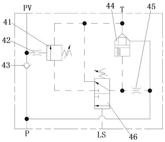
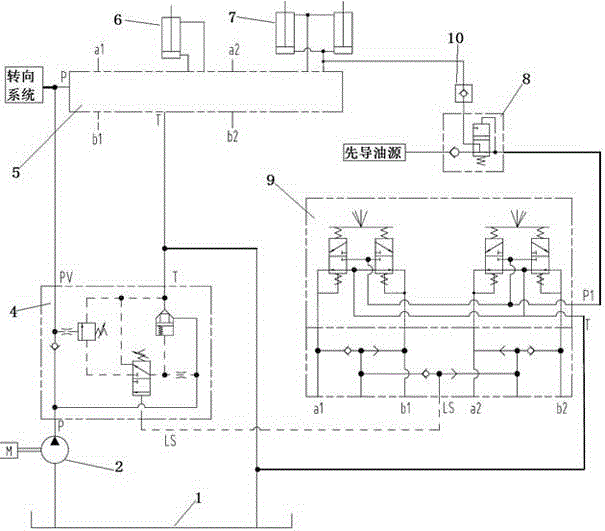
[0018] Such as figure 1 As shown, the hydraulic control unloading valve 4 includes an oil inlet P, an oil outlet PV, an overflow T, a safety valve 41, a two-position three-way valve 46, an overflow valve 44, and an orifice 45. Between the oil port P and the oil outlet PV, there is a first one-way valve 43 that conducts one-way in the direction of the oil outlet PV. The hydraulic control end of the safety valve 41 is connected between the first one-way valve 43 and the oil outlet PV. A second orifice 42 is provided between the liquid control end of the safety valve 41 and the oil outlet PV. The outlet of the safety valve 41 communicates with the overflow port T, the inlet of the safety valve 41 communicates with one outlet of the two-position three-way valve 46, the other outlet of the two-position three-way valve 46 communicates with the overflow port T, and the oil inl...


PUM


Abstract

The invention relates to a hydraulic control unloading valve. The hydraulic control unloading valve solves the problem that energy losses are caused due to the fact that an existing unloading valve can only achieve high-pressure unloading. A one-way valve which conducts one-way connection in the direction of an oil outlet PV is arranged between an oil inlet P and the oil outlet PV in the hydraulic control unloading valve. The hydraulic control end of a safety valve is connected between the one-way valve and the oil outlet PV. An outlet of the safety valve is communicated with an overflowing opening T. An inlet of the safety valve is communicated with one outlet of a two-position three-way valve, and the other outlet of the two-position three-way valve is communicated with the overflowing opening T. The oil inlet P is respectively communicated with the inlet of the two-position three-way valve and the hydraulic control end of an overflowing valve through an orifice. An oil inlet of the overflowing valve is communicated with the oil inlet P. An oil outlet of the overflowing valve is communicated with the overflowing opening T. The hydraulic control end of the two-position three-way valve is communicated with an LS opening of the hydraulic control end. The hydraulic control unloading valve has no overflowing losses or neutral-position opening losses or high-pressure unloading losses, and is low in energy consumption and cooling power, and the service life of liquid oil is long.

Description

technical field [0001] The invention relates to a hydraulic component, in particular to a hydraulic control unloading valve. Background technique [0002] At present, in the hydraulic system using unloading valve, the unloading valve is generally a high-pressure unloading valve. When the pressure of the hydraulic system reaches the pressure set by the unloading valve, the hydraulic system realizes high-pressure unloading, and there is a large loss of high-pressure unloading; At the same time, under some working conditions of the hydraulic system, the actuator does not operate or performs micro-action, but the hydraulic oil supplied by the oil pump is provided to the actuator for action, and the remaining flow flows back to the oil tank through the main valve, resulting in a huge Median loss and throttling loss; thus, the hydraulic system generates a lot of heat and consumes a lot of energy. Contents of the invention [0003] The object of the present invention is to provi...

Claims


Application Information

Patent Timeline
Patent Type & Authority Patents(China)
IPC IPC(8): F15B20/00F15B13/06
Inventor 黄胜梁振国王允姜炜
Owner GUANGXI LIUGONG MASCH CO LTD
Why Eureka
Try Eureka