PCC (Large Diameter Pipe Pile by using Cast-in-place Concrete) energy pile and manufacturing method thereof

An energy pile and pile bottom technology, which is applied in the field of civil engineering, can solve the problems of inability to repair, damage, and small pile side surface area, and achieve the effects of convenient repair and maintenance, high energy transmission efficiency, and wide application range

Active Publication Date: 2012-12-05
HOHAI UNIV +1
View PDF8 Cites 44 Cited by
  • Summary
  • Abstract
  • Description
  • Claims
  • Application Information

AI Technical Summary

Problems solved by technology

Although this kind of energy pile does not increase the land area, it has the following disadvantages: (1) The U-shaped pipe is bound on the steel cage and buried in the concrete, and is deformed together with the pile body, which may easily cause deformation and damage to the pipe; ( 2) The U-shaped pipe is buried in the concrete, which cannot be recycled, reused, or repaired. Problems in the process of use cannot be remedied; Loss of heat source; (4) The U-shaped pipe is buried in the concrete, which causes stress concentration around the U-shaped pipe when the pile is stressed, which is not conducive to the stress of the pile body, prone to local damage, and the bearing capacity of the pile is reduced
(5) The cost of prefabricated piles is relatively high, and the diameter of prefabricated piles is generally small, that is, the surface area of ​​the pile side is small, and the heat collection capacity is limited
The inner and outer diameters of this pile type are both large, generally more than 1m. It has a large-diameter pile core, and a large internal space can be obtained by hollowing out the large-diameter pile core soil. Take advantage of

Method used


Image

  • PCC (Large Diameter Pipe Pile by using Cast-in-place Concrete) energy pile and manufacturing method thereof
  • PCC (Large Diameter Pipe Pile by using Cast-in-place Concrete) energy pile and manufacturing method thereof
  • PCC (Large Diameter Pipe Pile by using Cast-in-place Concrete) energy pile and manufacturing method thereof

Examples


Embodiment Construction

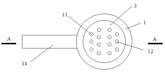
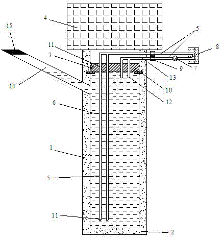
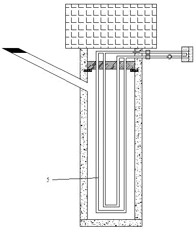
[0048] like Figure 1~Figure 4 As shown, a PCC energy pile is composed of PCC pile (1), heat transfer liquid (6), cover plate (3), bottom plate (2), heat pipe (5), heat collector (8), inspection channel ( 14) and other parts, PCC pile (1) pile bottom is completely closed with reinforced concrete to form the bottom plate (2); reinforced concrete cover plate (3) is set on the top of PCC pile; multiple holes are set on the cover plate (3), respectively Connect with the heat conduction pipe (5) of the water inlet hole (11) and the heat conduction pipe (5) of the water outlet hole (12); the cavity of the pipe pile is filled with heat conduction liquid (6); the heat conduction pipe (5) passes through the cover plate ( 3) The hole on the top goes deep into the heat-conducting liquid (6) in the cavity of the PCC pile (1); the heat-conducting pipe (5) is connected with the heat collector (8), and forms a circulation together with the cavity of the PCC pile (1) aisle. An inspection pa...


PUM


Abstract

The invention discloses a PCC (Large Diameter Pipe Pile by using Cast-in-place Concrete) energy pile. The PCC energy pile comprises a PCC pile, a heat conducting liquid, a cover plate, a bottom plate, a heat conducting pipe, a heat collecting device and an inspection channel, wherein the bottom of the PCC pile is fully closed; a cover plate with holes is arranged at the top of the PCC pile; prepared holes are formed in one side at the upper part of the PCC pile; the heat conducting liquid is filled up in a cavity in the PCC pile; the heat conducting pipe penetrates through the holes in the cover plate and extends into the heat conducting liquid in the cavity in the PCC pile; the heat conducting pipe extending into the cavity in the PCC pile can adopt opened and closed modes; the inspection channel is formed in the side wall of the PCC pile; and the heat conducting pipe is led out of the cavity in the PCC pile through the holes in the cover plate or the inspection channel and connected with the heat collecting device to form a circulating channel of the heat conducting liquid. The invention further discloses a manufacturing method for the pile. The manufacturing method comprises the technical steps as follows: pouring the PCC pile; excavating pile core soil; making a bottom plate; mounting the heat conducting pipe and the cover plate; filling the heat conducting liquid; and starting a ground heat pump for forming a loop. The PCC energy pile is convenient to overhaul and maintain, wide in application range and low in construction cost, does not influence the bearing capacity, and is an economic, efficient, energy-saving and emission-reducing pile.

Description

technical field [0001] The invention belongs to the technical field of civil construction engineering, and in particular relates to a PCC pile energy pile and a using method. Background technique [0002] Geothermal resources are a kind of clean energy with wide distribution, low cost and convenient use, and have broad development and application prospects. Ground source heat pump technology uses the relatively stable characteristics of underground soil, surface water, and groundwater temperature to transfer heat from low-level heat sources to places that need heating or heating in winter by consuming electric energy. The waste heat is transferred to the low-level heat source to achieve the purpose of cooling or cooling. Ground source heat pumps do not require artificial cold and heat sources, and can replace traditional heating methods such as boilers or municipal pipe networks and central air-conditioning systems. In winter, it replaces boilers to obtain heat from soil, ...

Claims


Application Information

Patent Timeline
Patent Type & Authority Applications(China)
IPC IPC(8): E02D5/34F24J3/08
CPCY02E10/10F24T10/40
Inventor 刘汉龙丁选明孔纲强吴宏伟陈育民
Owner HOHAI UNIV
Why Eureka
Try Eureka