Backlight unit using wire-grid polarizer and liquid crystal display apparatus employing the backlight unit

a backlight unit and polarizer technology, applied in the direction of lighting and heating apparatus, polarising elements, instruments, etc., can solve the problems of high cost, inability to increase the brightness of the lcd apparatus, and inability to manufacture additional products, so as to achieve efficient and low cost s-polarized light or p-polarized light

Inactive Publication Date: 2009-11-10
SAMSUNG DISPLAY CO LTD
View PDF9 Cites 44 Cited by
  • Summary
  • Abstract
  • Description
  • Claims
  • Application Information

AI Technical Summary

Benefits of technology

[0014]The present invention provides a backlight unit which can emit s-polarized light or p-polarized light efficiently and without loss using a wire-grid polarizer.

Problems solved by technology

Also, there is a limit to the increase in the brightness of the LCD apparatus.
However, the cost is high and additional manufacturing processing is needed for the DBEF to be attached to the backlight unit.
However, the brightness of the LCD apparatus cannot be improved without external light, and additional manufacturing process is needed to form the wire-grid polarizer when manufacturing LCD panels.

Method used


Image

  • Backlight unit using wire-grid polarizer and liquid crystal display apparatus employing the backlight unit
  • Backlight unit using wire-grid polarizer and liquid crystal display apparatus employing the backlight unit
  • Backlight unit using wire-grid polarizer and liquid crystal display apparatus employing the backlight unit

Examples


Embodiment Construction

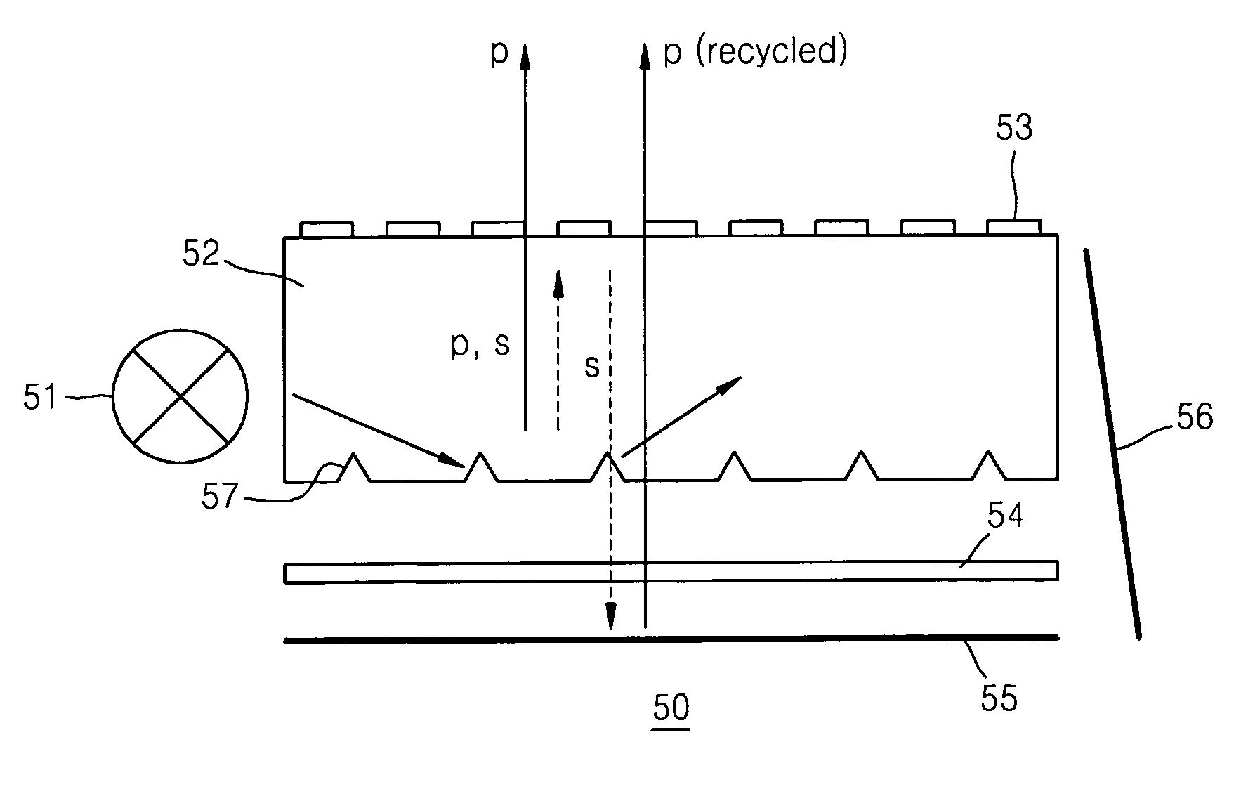
[0034]FIG. 4A is a cross-sectional view of a backlight unit 30 to using a wire-grid polarizer 33 according to an exemplary embodiment of the present invention. Referring to FIG. 4A, the backlight unit 30 includes a light source 31 placed at a side of a light guide plate 32, a wire-grid polarizer 33 formed on the upper surface of the light guide plate 32, and a polarization converter 34 and a lower reflection panel 35 placed below the light guide plate 32. The light source 31 may be a point light sources such as a light emitting diode (LED) or a linear light source such as a cold cathode fluorescent lamp (CCFL). The light guide plate 32 can be formed of a plastic with a high light transmittance such as polymethyl methacrylate (PMMA).

[0035]Light is emitted from the light source 31 at a predetermined angle, is incident on a side of the light guide plate 32 and proceeds inside the light guide plate 32. Since the light guide plate 32 has a high refractive index and a high light-transmitt...


PUM


Abstract

A backlight unit, which can emit one of s-polarized light and p-polarized light using wire-grid polarizer, and a liquid crystal display apparatus employing the backlight unit are provided. The backlight unit includes: a light source radiating light; a light guide plate disposed with the light source at a lateral side of the light guide plate, guiding the light incident on the lateral side from the light source; a wire-grid polarizer formed on a predetermined layer of the light guide plate transmitting a first polarized component of the light through the predetermined layer and reflecting a second polarized component of light; a reflector reflecting the light to un upper surface of the light guide plate; and a polarization converter changing a polarization of the light not emitted through the upper surface of the light guide plate.

Description

CROSS-REFERENCE TO RELATED PATENT APPLICATION[0001]This application claims priority from Korean Patent Application No. 10-2005-0079989, filed on Aug. 30, 2005, in the Korean Intellectual Property Office, the disclosure of which is incorporated herein in its entirety by reference.BACKGROUND OF THE INVENTION[0002]1. Field of the Invention[0003]Apparatuses and methods consistent with the present invention relate to a backlight unit and a liquid crystal display (LCD) apparatus, and more in particular, to a backlight unit in which one of s-polarized light or p-polarized light can be emitted by using wire-grid polarizer and an LCD apparatus employing the backlight unit.[0004]2. Description of the Related Art[0005]FIG. 1 illustrates a conventional liquid crystal display (LCD) apparatus. Referring to FIG. 1, the LCD apparatus includes an LCD panel 10 and a backlight unit 20 installed on a rear substrate of the LCD panel 10 to radiate light to the LCD panel 10. The LCD itself does not genera...

Claims


Application Information

Patent Timeline
Patent Type & Authority Patents(United States)
IPC IPC(8): F21V9/14F21V7/04G02B5/30
CPCG02F1/13362G02B6/0056G02B6/0038G02B6/0055G02F2001/133548G02F1/133548G02F1/1335
Inventor NESTERENKO, DMITRYCHOI, HWAN-YOUNG
Owner SAMSUNG DISPLAY CO LTD
Why Eureka
Try Eureka