
Piston ring fatigue testing machine and fatigue testing method

A technology of fatigue testing machine and piston ring, which is applied in the testing of mechanical components, testing of machine/structural components, measuring devices, etc. It can solve the problems of unstable speed, easy falling off of piston rings, and complicated mechanism, so as to improve the degree of automation , Improve work efficiency, improve the effect of test accuracy

Active Publication Date: 2016-10-26
CHINA THREE GORGES UNIV
View PDF5 Cites 13 Cited by
  • Summary
  • Abstract
  • Description
  • Claims
  • Application Information

AI Technical Summary

Problems solved by technology

The traditional piston ring fatigue testing machine has unstable speed and large vibration during operation, the piston ring is easy to fall off, and the mechanism is relatively complicated, which cannot accurately simulate the fatigue life of the piston ring, and the measured life of the piston ring fatigue test varies greatly , the existing equipment cannot meet the detection requirements

Method used


Image

  • Piston ring fatigue testing machine and fatigue testing method
  • Piston ring fatigue testing machine and fatigue testing method
  • Piston ring fatigue testing machine and fatigue testing method

Examples


Embodiment 1

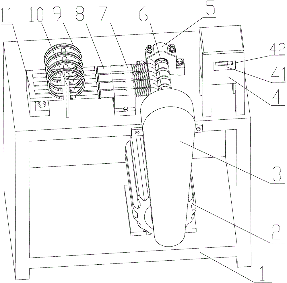
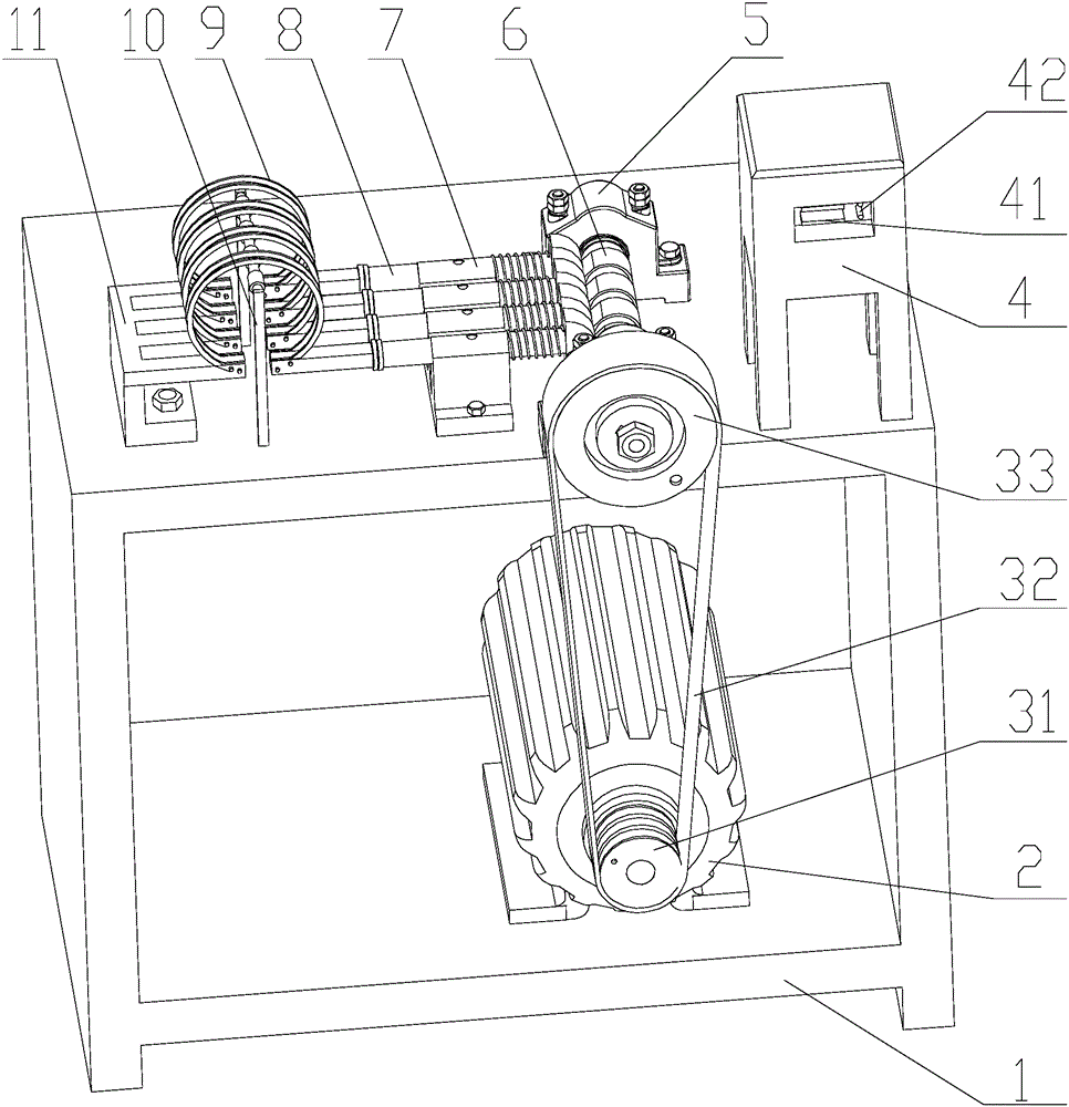
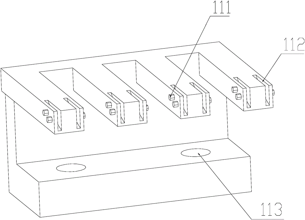
[0037] Such as Figure 1-6 Shown, a kind of piston ring fatigue testing machine, it comprises base 1, and the lower end of described base 1 is fixedly installed with three-phase asynchronous motor 2, and described motor 2 is connected with camshaft 6 through belt pulley 3, and on described camshaft 6 The cam and one end of the spring push rod 8 form a cam push rod transmission fit, the middle part of the spring push rod 8 forms a sliding fit with the guide rail 7, and the other end of the spring push rod 8 is connected to the piston ring clamp body 11, and the piston A transmission sensor 10 is arranged in the middle of the ring clamp body 11 , and the sensor 10 is electrically connected to the control cabinet 4 , a counter is arranged in the control cabinet 4 , and the control cabinet 4 is installed on the top of the base 1 . The fatigue life of the piston ring can be studied through the above fatigue testing machine, and the structure of the equipment is simplified through t...

Embodiment 2

[0047] A method of performing a fatigue test using any ring fatigue testing machine, which includes the following steps:

[0048] S1: fix the two ends of the openings of the eight piston rings 9 to be tested on the fixed part and the two ends of the movable part of the piston ring clamp body 11 respectively, and fix them with screws;

[0049] S2: According to the model of the piston ring 9 to be detected and the use environment, set the motion law of the camshaft 6, set it to a quintic polynomial motion law, and ensure that the stroke h of the push rod is the free opening size of the piston ring , set the number of fatigue tests through the button on the control cabinet 4;

[0050] S3: By starting the motor 2, the driving wheel 31 is driven by the motor 2, the driving wheel 31 drives the driven wheel 33 to rotate through the belt 32, the driven wheel 33 is connected with the camshaft 6 through a flat key, and the power is transmitted to the spring push rod 8, and the spring pu...


PUM


Abstract

The invention discloses a piston ring fatigue testing machine and a fatigue testing method. A pedestal is included. A lower end of the pedestal is fixedly provided with a three-phase asynchronous motor. The motor is connected to a camshaft through a belt pulley. A cam on the camshaft and one end of a spring push rod form cam push rod transmission cooperation. A middle portion of the spring push rod and a guide rail form sliding fit. The other end of the spring push rod is connected to a piston ring fixture body. A middle portion of the piston ring fixture body is provided with a sensor. The sensor and a control cabinet are electrically connected. A counter is arranged in the control cabinet. The control cabinet is installed on a top of the pedestal. The structure is simple and operation is convenient. Fatigue lives of eight groups of piston rings can be detected simultaneously. A condition that one piston ring generates an abnormal value during detection is prevented. One range where a data difference can be allowed and accepted is convenient to analyze. A force bearing condition of the piston ring in a fuel engine can be simulated and an effect of detecting whether the fatigue life of the piston ring accords with a design requirement is reached.

Description

technical field [0001] The invention relates to an internal piston ring fatigue test device of a fuel engine, in particular to a piston ring fatigue test machine and a fatigue test method. Background technique [0002] The present invention mainly studies the structural forms of engine piston rings which are relatively common at home and abroad and designs a common piston ring fatigue testing machine structure in the market with a general basic diameter between 85mm and 135mm. It is an important part of the engine. Parts, their service life directly affects the engine overhaul interval. Piston ring fatigue testing machine is a very important testing machine, and it is a mechanical force testing machine used to test the mechanical properties of piston ring materials such as tension and compression. The traditional piston ring fatigue testing machine has unstable speed and large vibration during operation, the piston ring is easy to fall off, and the mechanism is relatively c...

Claims


Application Information

Patent Timeline
Patent Type & Authority Applications(China)
IPC IPC(8): G01M13/00
CPCG01M13/00
Inventor 王道吴海华
Owner CHINA THREE GORGES UNIV
Learn More