Electric quantity display system and notebook computer with same
A notebook computer and power display technology, applied in the direction of measuring electrical variables, measuring electricity, measuring devices, etc., can solve the problems of service life impact, long time, etc., and achieve the effect of realizing functions
- Summary
- Abstract
- Description
- Claims
- Application Information
AI Technical Summary
Problems solved by technology
Method used
Image

Examples
Embodiment Construction
[0018] The present invention will be described in further detail below in conjunction with the accompanying drawings and specific embodiments, but not as a limitation of the present invention.
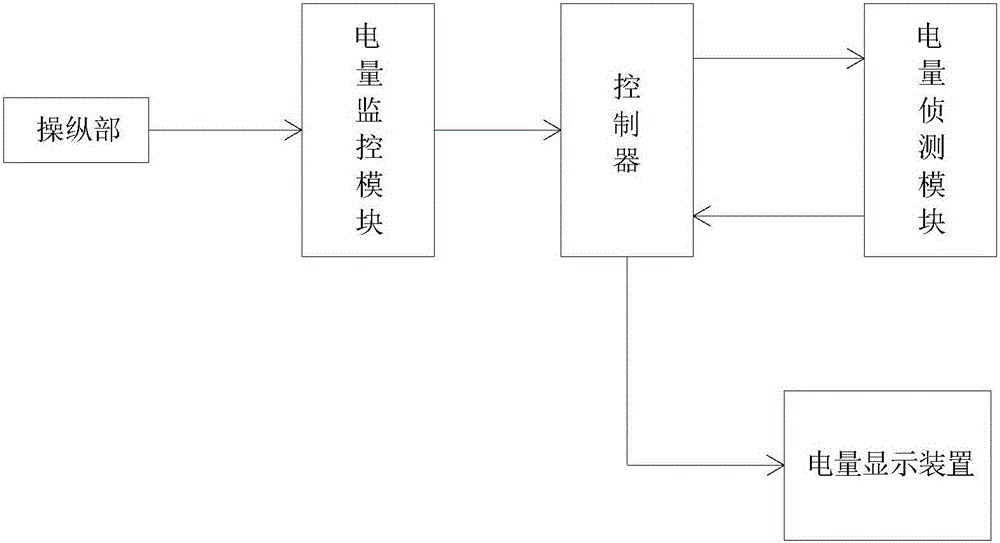
[0019] The invention provides a power display system, from figure 1 It can be seen from the figure that the power display system mainly includes a control unit, a power monitoring module, a controller, a power detection module and a power display device.
[0020] Wherein, the operating part is arranged on the upper surface of the host end of the notebook computer (that is, the surface of the notebook computer on which the keyboard is arranged), and is used for manipulating the power monitoring module to send a power display request signal to the controller. Preferably, the manipulating part may be in the form of a power key. When the user presses the power key, the power monitoring module is activated, thereby sending a power display request signal to the controller. The controller is...
PUM
 Abstract
Description
Claims
Application Information
 - Generate Ideas
- Intellectual Property
- Life Sciences
- Materials
- Tech Scout
- Unparalleled Data Quality
- Higher Quality Content
- 60% Fewer Hallucinations
Browse by: Latest US Patents, China's latest patents, Technical Efficacy Thesaurus, Application Domain, Technology Topic, Popular Technical Reports.
© 2025 PatSnap. All rights reserved.Legal|Privacy policy|Modern Slavery Act Transparency Statement|Sitemap|About US| Contact US: help@patsnap.com