
A Concealed Installation Microwave Sensor and Its Noise Suppression Method

A microwave sensor, hidden technology, applied in instruments, measuring devices, transportation and packaging, etc., can solve the problem of increasing price costs and installation and debugging time costs, reducing the signal-to-noise ratio and stability of microwave sensors, reducing the detection area of ​​microwave sensors, etc. problems, to achieve improved stability and detection range, simple Doppler noise, and improved design aesthetics

Active Publication Date: 2019-05-24
B E A ELECTRONICS BEIJING
View PDF5 Cites 0 Cited by
  • Summary
  • Abstract
  • Description
  • Claims
  • Application Information

AI Technical Summary

Problems solved by technology

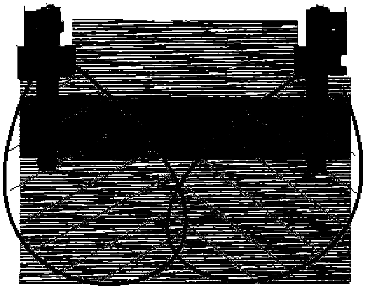
[0014] like figure 1 As shown, the existing hidden installation microwave detection device can well solve the problem of the overall aesthetics of the escalator, but when it is installed inside the escalator cavity with a full metal panel structure, the microwave will undergo complex reflection and superposition in the inner space of the escalator
When the escalator is started, the mechanical movement and vibration inside the escalator will cause the Doppler effect, which is Doppler interference noise, which reduces the signal-to-noise ratio and stability of the microwave sensor and interferes with the microwave sensor normal operation, even false detection occurs
In this regard, the general solution is to reduce the sensitivity of the product, resulting in a significant reduction in the detection area of ​​conventional microwave sensors
The existing solutions basically use two sensors to work together to achieve the purpose that the detection area can completely cover the entrance area of ​​the escalator, which increases the price cost and installation and commissioning time cost

Method used


Image

  • A Concealed Installation Microwave Sensor and Its Noise Suppression Method
  • A Concealed Installation Microwave Sensor and Its Noise Suppression Method
  • A Concealed Installation Microwave Sensor and Its Noise Suppression Method

Examples


Embodiment Construction

[0056] In order to make the object, technical solution and advantages of the present invention clearer, the present invention will be further described in detail below in conjunction with the accompanying drawings. It should be understood that the specific implementation cases described here are only used to explain the present invention, and are not intended to limit the present invention.

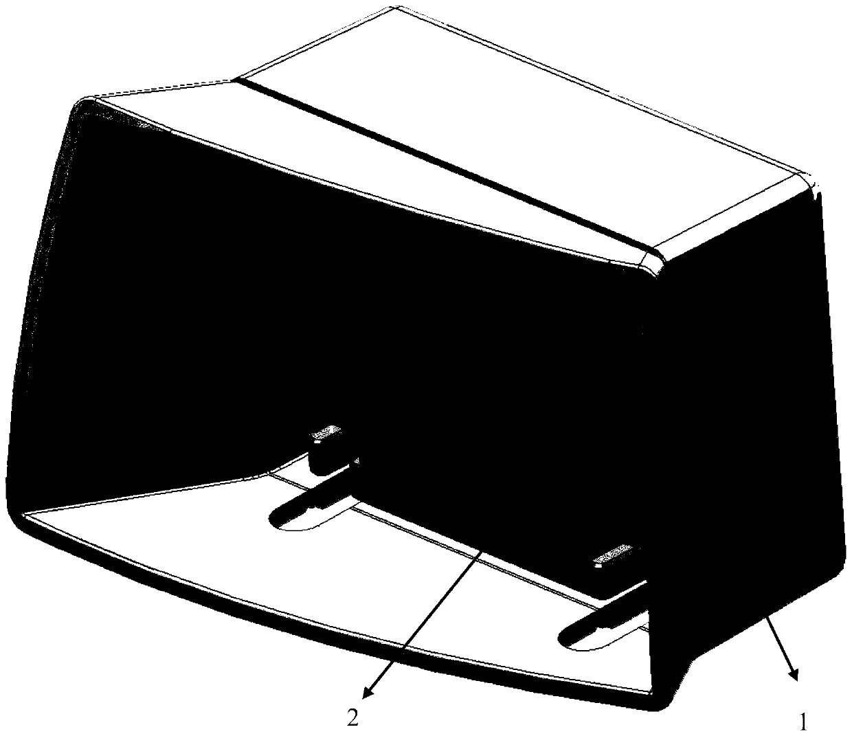
[0057] According to one embodiment of the present invention, a concealed installation microwave sensor includes a housing and a microwave sensor. Such as figure 2 As shown, the shell is divided into a front shell 1 and a rear shell 2; wherein, the microwave sensor is installed in the rear shell 2, and the rear shell 2 adopts a half-wrapped shell design, and the opening surface of the rear shell 2 is a microwave antenna. On one side, the inner contour of the rear housing 2 is designed using microwave simulation technology. The front shell 1 is overlaid on the rear shell 2, and the front...


PUM


Abstract

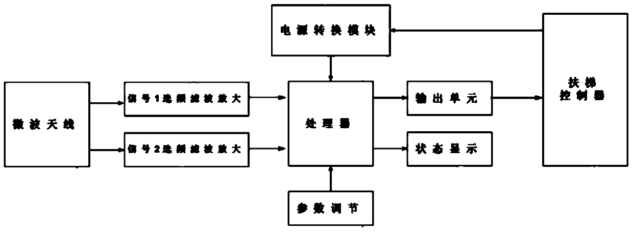
Aiming at the deficiencies of the prior art, the present invention provides a concealed installation microwave sensor, including a shell and a microwave sensor. By adopting a special shell design method, the escalator microwave sensor solves the problem of the product while ensuring that the detection area is large enough. Probability of false triggering. The microwave sensor includes: a microwave antenna, a signal frequency-selective filter amplifier circuit unit, a processor, a power supply module and a control module. After analyzing and judging the movement trend of the moving object, a control instruction is formed and sent to the control module. The control module controls the movement of the external equipment according to the obtained control instruction, and the power supply module provides electric energy for each component. The invention has the advantages that it can be concealedly installed inside an escalator with a complex all-metal panel structure, and only one microwave sensor can completely detect the entire escalator entrance area.

Description

technical field [0001] The invention belongs to the technical field of automatic sensor control, and in particular relates to a concealed installation microwave sensor and a noise suppression method thereof. Background technique [0002] Escalators are very common and indispensable automatic equipment in people's daily life. However, the power consumption of escalators is relatively large when they are running at full speed. When no one is on the escalator, the escalator is still running without load, which consumes a lot of energy. In order to realize the demand of green energy saving, it is required that when no one takes the escalator, the escalator will automatically switch to the idle energy-saving mode or the stop mode; when the human body is detected to be close to a certain area of ​​the escalator, the escalator will automatically switch to the full-speed operation mode in advance. In this way, a specific sensor device needs to be installed at the entrance of the esc...

Claims


Application Information

Patent Timeline
Patent Type & Authority Patents(China)
IPC IPC(8): G01S13/88G01S7/02B66B29/00
CPCB66B29/00G01S7/02G01S13/88G01S7/027
Inventor 刘冀湘苏丹王忠
Owner B E A ELECTRONICS BEIJING
Learn More