
Fingerprint identification device, driving method, manufacturing method and display device

A fingerprint identification and device technology, which is applied in character and pattern recognition, acquisition/organization of fingerprints/palmprints, instruments, etc., can solve the problems of increasing manufacturing costs, the distance between fingers and sensors should not be too far, and achieve the effect of reducing manufacturing costs

Active Publication Date: 2016-10-26
BOE TECH GRP CO LTD +1
View PDF4 Cites 7 Cited by
  • Summary
  • Abstract
  • Description
  • Claims
  • Application Information

AI Technical Summary

Problems solved by technology

[0004] Since the distance between the finger and the sensor in the solution in the prior art cannot be too far, glass with a certain thickness can be arranged between the finger and the sensor, but holes need to be made on the glass to place the sensor, thereby increasing the manufacturing cost

Method used


Image

  • Fingerprint identification device, driving method, manufacturing method and display device
  • Fingerprint identification device, driving method, manufacturing method and display device
  • Fingerprint identification device, driving method, manufacturing method and display device

Examples


Embodiment Construction

[0037] In order to enable those skilled in the art to better understand the technical solution of the present invention, the fingerprint recognition device, its driving method, manufacturing method and display device provided by the present invention will be described in detail below with reference to the accompanying drawings.

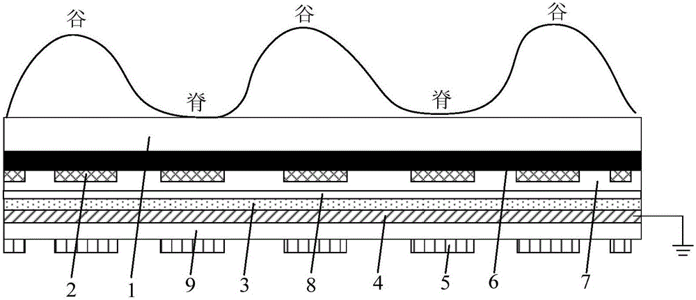
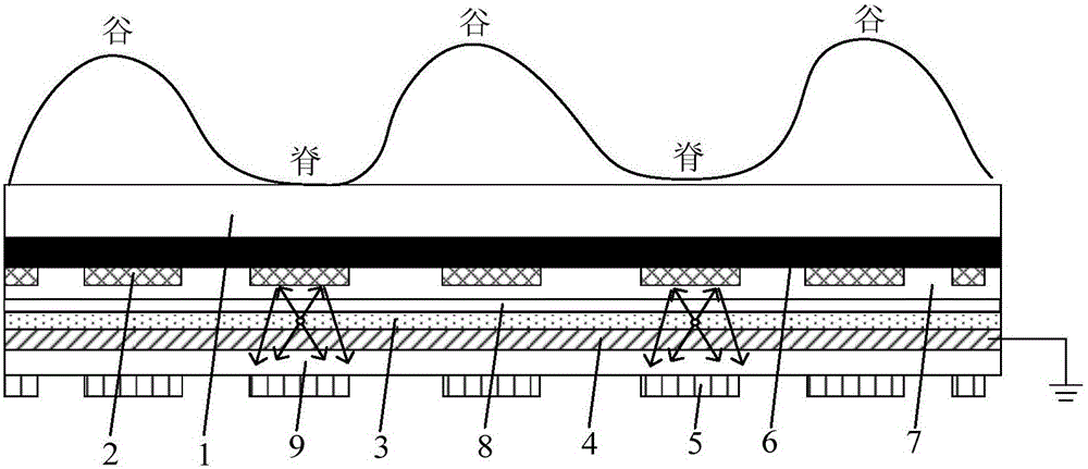
[0038] figure 1 A schematic structural diagram of a fingerprint identification device provided in Embodiment 1 of the present invention, as shown in figure 1 As shown, the fingerprint identification device includes: a cover plate 1 and a first electrode 2 , a light emitting layer 3 , a second electrode 4 and a light sensor 5 located above the cover plate 1 and arranged in sequence. The first electrode 2 is used to apply the first voltage when the specific position of the finger corresponding to the first electrode 2 generates static electricity; the second electrode 4 is used to apply the second voltage; Light is emitted under the action of the volta...


PUM


Abstract

The invention discloses a fingerprint identification device, a driving method, a manufacturing method and a display device. The fingerprint identification device comprises a cover plate, and first electrodes, a light emitting layer, a second electrode and light sensors which are disposed above the cover plate and are arranged sequentially. The first electrodes are used for loading a first voltage when static electricity is produced at specific positions, corresponding to the first electrodes, of a finger. The second electrode is used for loading a second voltage. The light emitting layer is used for emitting light under the action of the voltage difference between the first voltage and the second voltage. The light sensors are used for converting the light emitted by the light emitting layer into a current, and the current is used to identify the fingerprints in the specific positions of the finger. The function of fingerprint identification is achieved by arranging the first electrodes, the second electrode, the light emitting layer and the light sensors on the cover plate. There is no need to open a hole in the cover plate. Thus, the manufacturing cost is reduced.

Description

technical field [0001] The invention relates to the field of display technology, in particular to a fingerprint recognition device, a driving method, a manufacturing method and a display device. Background technique [0002] In the late 1990s, the Hong Kong Polytechnic University and Tsinghua University pioneered the research field of fingerprint recognition technology. Fingerprint recognition has the advantages of high precision, fast speed, low price, and high user acceptance. With full attention, many universities and scientific research institutions at home and abroad have joined in this research field and achieved a series of results. [0003] At present, the application of fingerprint identification technology is more and more extensive. In the prior art, most of the fingerprint identification functions are formed based on self-capacitance or mutual-capacity. [0004] Since the distance between the finger and the sensor cannot be too far in the solution in the prior ...

Claims


Application Information

Patent Timeline
IPC IPC(8): G06K9/00
CPCG06V40/1318
Inventor 刘英明董学陈小川王海生丁小梁邓立广杨盛际赵卫杰
Owner BOE TECH GRP CO LTD
Learn More