communication device
A communication device and output signal technology, which is applied in the direction of transportation and packaging, signal transmission system, general control system, etc., can solve the problem of short data update period and achieve the effect of increasing the frequency of data update
- Summary
- Abstract
- Description
- Claims
- Application Information
AI Technical Summary
Problems solved by technology
Method used
Image
Examples
no. 1 example
[0033] will refer to Figures 1 to 8 A first embodiment of the present disclosure is described.
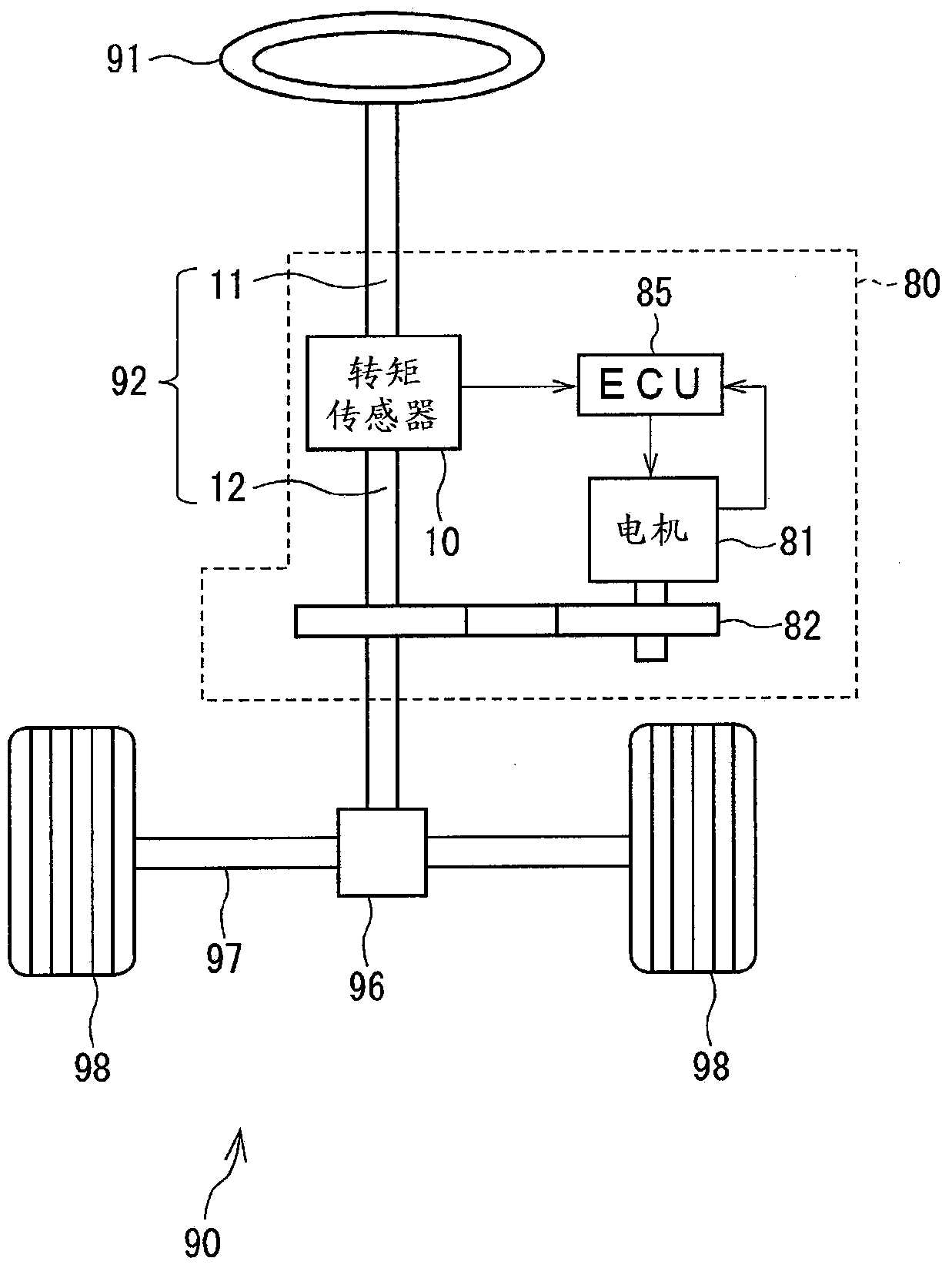
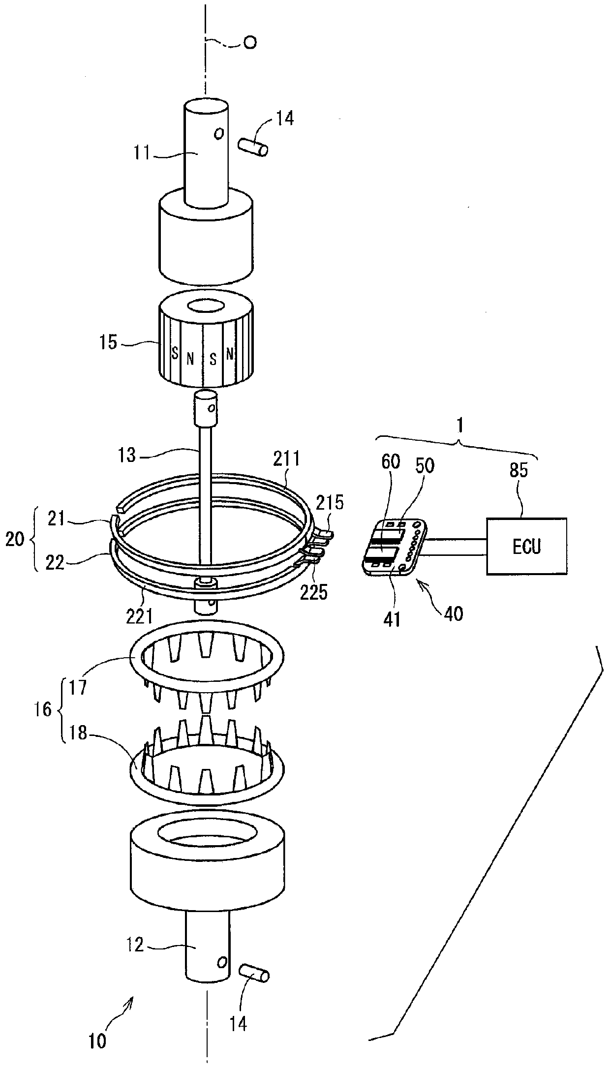
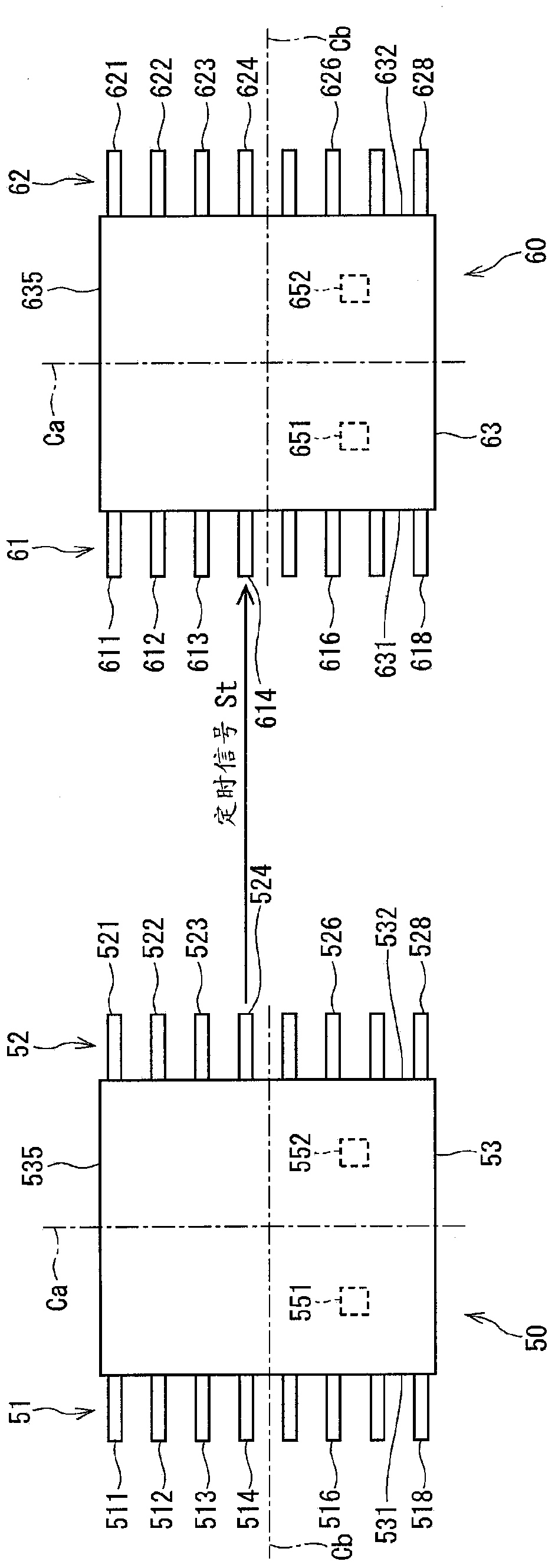
[0034] Such as figure 1 and 2 As shown in , the communication device 1 is provided with a primary magnetic sensor 50, a secondary magnetic sensor 60, and an ECU 85 as a control unit. The communication device is applied to, for example, an electric power steering device 80 for assisting a steering operation of a vehicle.
[0035] figure 1 The overall configuration of a steering system 90 provided with an electric power steering device 80 is illustrated.
[0036] The steering wheel 90 is connected to a steering shaft 92 .
[0037] The steering shaft 92 includes an input shaft 11 as a first shaft and an output shaft 12 as a second shaft. The input shaft 11 is connected to a steering wheel 91 . A torque sensor 10 that detects torque applied to a steering shaft 92 is provided between the input shaft 11 and the output shaft 12 . A pinion gear 96 is provided at the end of the out...
no. 2 example
[0135] Figure 9 and 10 A second embodiment of the present disclosure is illustrated.
[0136] The communication device 2 of the present embodiment is provided with a magnetic sensor 70 and an ECU 85 .
[0137] The sensor unit 45 includes a magnetic sensor 70 mounted on the substrate 41 .
[0138] The magnetic sensor 70 includes a first terminal group 71 , a second terminal group 72 , a sealing portion 73 , a main sensor portion 55 and a sub sensor portion 65 .
[0139] The first terminal group 71 protruding from the first side 731 of the sealing portion 73 includes 8 terminals, specifically, the first to eighth terminals 711 to 718 are arranged in this order from the first end 735 . The second terminal group 72 protruding from the second side 732 of the sealing part 73 includes 8 terminals, specifically, the first to eighth terminals 721 to 728 are arranged in this order from the first end 735 . exist Figure 9 In , reference numerals of terminals whose functions are not...
no. 3 example
[0149] Figures 11 to 14 A third embodiment of the present disclosure is illustrated.
[0150] Such as Figure 11 As shown in , the communication device 3 of this embodiment is provided with a primary magnetic sensor 150, a secondary magnetic sensor 160, and an ECU 86 (ie, a controller) as a control unit.
[0151] The ECU 86 controls the driving of the motor 81 according to the steering torque calculated based on the output signals Sd11 , Sd12 output from the magnetic sensors 150 , 160 . The ECU 86 includes a signal acquisition unit 87 and a trigger signal generation unit 88 .
[0152] The trigger signal generator 88 generates a trigger signal Trg1 for requesting transmission of the output signal Sd21. The trigger signal Trg1 is transmitted to the main sensor section 155 through the second terminal 512 which is a communication terminal of the first terminal group 51 .
[0153] The trigger signal generator 88 generates a trigger signal Trg2 for requesting transmission of th...
PUM
 Abstract
Description
Claims
Application Information
 - R&D
- Intellectual Property
- Life Sciences
- Materials
- Tech Scout
- Unparalleled Data Quality
- Higher Quality Content
- 60% Fewer Hallucinations
Browse by: Latest US Patents, China's latest patents, Technical Efficacy Thesaurus, Application Domain, Technology Topic, Popular Technical Reports.
© 2025 PatSnap. All rights reserved.Legal|Privacy policy|Modern Slavery Act Transparency Statement|Sitemap|About US| Contact US: help@patsnap.com


