
Permanent magnetic motor and rotor thereof

A technology of permanent magnet motor and motor rotor, applied in the direction of magnetic circuit rotating parts, magnetic circuit, electrical components, etc., can solve the problem of difficult to adjust the magnetic field strength

Inactive Publication Date: 2016-10-26
SHANGHAI DIANJI UNIV
View PDF5 Cites 0 Cited by
  • Summary
  • Abstract
  • Description
  • Claims
  • Application Information

AI Technical Summary

Problems solved by technology

However, once the magnetic steel structure of the permanent magnet motor is fixed, it is difficult to adjust the strength of its magnetic field.
[0004] At present, the existing technology has changed the magnetization direction of the tangential permanent magnet, including 90°, 60°, 30°, etc.; start with structure

Method used


Image

  • Permanent magnetic motor and rotor thereof
  • Permanent magnetic motor and rotor thereof
  • Permanent magnetic motor and rotor thereof

Examples


Embodiment Construction

[0024] In order to make the above objects, features and advantages of the present invention more comprehensible, specific implementations of the present invention will be described in detail below in conjunction with the accompanying drawings.

[0025] Embodiments of the present invention will now be described in detail with reference to the accompanying drawings. Reference will now be made in detail to the preferred embodiments of the invention, examples of which are illustrated in the accompanying drawings. Wherever possible, the same numbers will be used throughout the drawings to refer to the same or like parts. In addition, although the terms used in the present invention are selected from well-known and commonly used terms, some terms mentioned in the description of the present invention may be selected by the applicant according to his or her judgment, and the detailed meanings thereof are set forth herein described in the relevant section of the description. Furtherm...


PUM


Abstract

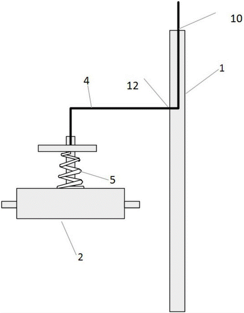
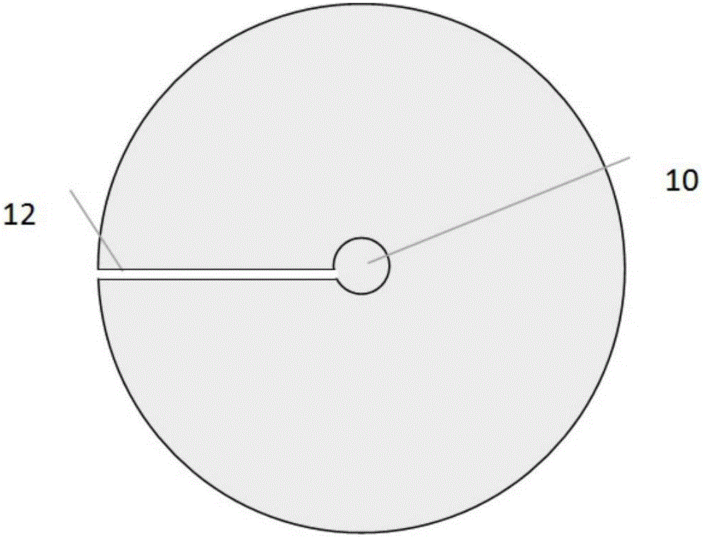
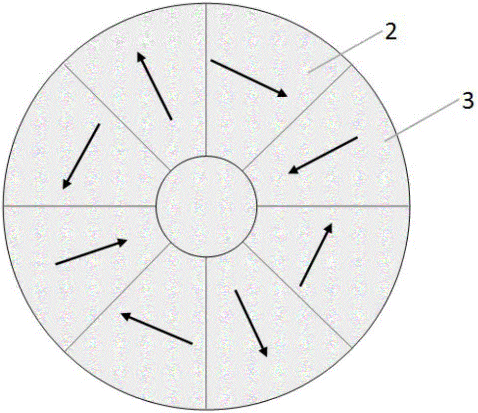
The invention relates to a permanent magnetic motor and a rotor thereof. The rotor of the permanent magnet motor comprises a rotor core and a motor shaft that penetrates the rotor core, the rotor core is provided with tangential and radial permanent magnets, the rotor core is provided with a non-magnetic-conductive connecting piece, and one end of the non-magnetic-conductive connecting piece is connected to the tangential permanent magnets so that the tangential permanent magnets retract towards the internal of the rotor core. According to the invention, the tangential permanent magnets retract to reduce the air-gap flux density and achieve the goals of flux weakening and speed increasing.

Description

technical field [0001] The invention relates to the technical field of motors, in particular to a permanent magnet motor. Background technique [0002] With the rapid development of the economy, the problems of environmental pollution and resource depletion have become obstacles to the development of human society, and energy conservation and emission reduction have become the main tone of economic development in various countries. As an indispensable part of the development of the national economy, the motor plays an important role in achieving the goal of energy conservation and emission reduction. With the development of science and technology, new materials are constantly coming out, especially the continuous development of high-performance rare earth permanent magnet materials, which has laid an important foundation for the emergence of high-performance permanent magnet motors. Rare earth permanent magnet motors have the characteristics of small size, low energy consum...

Claims


Application Information

Patent Timeline
IPC IPC(8): H02K1/27
CPCH02K1/272H02K2213/09
Inventor 田玉冬何超
Owner SHANGHAI DIANJI UNIV
Learn More