

Permanent magnet motor rotor capable of automatic weaking magnet following rotation speed
A permanent magnet motor and automatic technology, applied in the direction of magnetic circuit rotating parts, magnetic circuit shape/style/structure, etc., can solve the problems of system efficiency drop, low torque, and rotor flux leakage, etc., to improve utilization efficiency, The effect of increasing torque and reducing flux leakage
- Summary
- Abstract
- Description
- Claims
- Application Information
AI Technical Summary
Problems solved by technology
Method used
Image

Examples
specific Embodiment approach 1
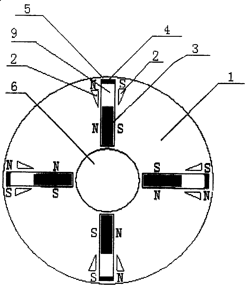
[0006] Specific implementation mode one: the following combination figure 1 This embodiment will be specifically described. It consists of a rotor core 1, a number of main pole permanent magnets 3, and a number of auxiliary permanent magnets 4. The rotor core 1 is cylindrical, and a number of radial slide grooves 9 are evenly distributed in the rotor core 1. Each of the A main pole permanent magnet 3 is inlaid in the radial chute 9 and the length of the main pole permanent magnet 3 is shorter than the radial chute 9, and on the top wall of the radial chute 9, it is connected with the The permanent magnets 3 are fixed with auxiliary permanent magnets 4 at intervals, the main pole permanent magnets 3 and the auxiliary permanent magnets 4 are both tangentially magnetized and the main pole permanent magnets 3 in the same radial slide groove 9 The magnetization direction of the auxiliary permanent magnet 4 is the same, the polarities of the adjacent side surfaces of the two adjac...
specific Embodiment approach 2
[0007] Specific implementation mode two: the following combination figure 1 This embodiment will be specifically described. A magnetic isolation slot 2 is respectively opened on both sides of the radial chute 9, and the two magnetic isolation slots 2 take the radial chute 9 as the center of symmetry, and the magnetic isolation slot 2 is opened in the radial direction. at the outer end of the chute 9. Other components and connections are the same as those in Embodiment 1. In this embodiment, "the reluctance of the rotor core 1 at the inner end of the radial chute 9 is smaller than the reluctance of the rotor core 1 at the outer end of the radial chute 9" is realized by separating the magnetic slot 2, the structure is simple, and the process is easy to realize . The function of the magnetic isolation groove 2 is to reduce the magnetic flux sent by the main pole permanent magnet 3 when the main pole permanent magnet 3 moves outwards into its position, so its size and shape ar...
specific Embodiment approach 3
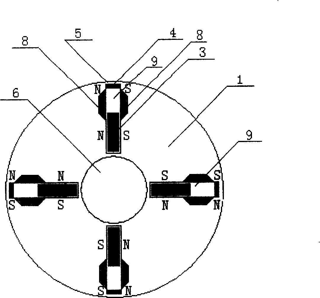
[0008] Specific implementation mode three: the following combination figure 2 This embodiment will be specifically described. The difference between this embodiment and the second embodiment is that the rotor core 1 also includes a non-magnetically conductive plate 8, and the non-magnetically conductive plate 8 is arranged on both sides of the radial chute 9 and is located in the radial chute 9. at the outer end. In this embodiment, "the reluctance of the rotor core 1 at the inner end of the radial chute 9 is smaller than the reluctance of the rotor core 1 at the outer end of the radial chute 9" is realized by setting the non-magnetic conductive plate 8, and the two non-magnetic conductive plates 8 is also equivalent to the auxiliary slideway of the main pole permanent magnet 3, so that the main pole permanent magnet 3 can slide smoothly in the radial slide groove 9. Other compositions and connections are the same as those in Embodiment 2.
PUM
 Abstract
Description
Claims
Application Information