Efficient transmission of digital return path data in cable television return path

a technology of return path and digital return path, which is applied in the direction of two-way working system, selective content distribution, television system, etc., can solve the problems of high cost of such high-speed optical equipment, inability to take information back from subscribers, and limit the bandwidth of optical equipment, so as to reduce the number of bits that are transported, suitable for high-speed operations, and the accuracy of the analog return signal is not substantially compromised

Active Publication Date: 2010-07-06
II VI DELAWARE INC
View PDF93 Cites 11 Cited by
  • Summary
  • Abstract
  • Description
  • Claims
  • Application Information

AI Technical Summary

Benefits of technology

[0010]An embodiment of the present invention is a cable television return path at which analog return signals are converted to digital format and encoded, and then transmitted across an optical link to a hub. At the hub, the encoded digital signal is decoded and converted to produce an analog signal that is a close approximation of the analog return signal. The encoding scheme of the present embodiment is efficient in reducing the number of bits that are transported across the optical link. Yet, the accuracy of the analog return signal is not substantially compromised. Furthermore, the encoding scheme of the present embodiment is simple, suitable for high-speed operations and cost-effective.

Problems solved by technology

Since the purpose was to distribute television channels throughout a community, the systems were designed to be one-way and did not have the capability to take information back from subscribers to the head end.
Naturally, the costs of such high-speed optical equipment are high.
Limits on the bandwidth of the optical equipment also restrict the number of analog return signals that can be bundled together for transmission on the same optical fiber.

Method used


Image

  • Efficient transmission of digital return path data in cable television return path
  • Efficient transmission of digital return path data in cable television return path
  • Efficient transmission of digital return path data in cable television return path

Examples


Embodiment Construction

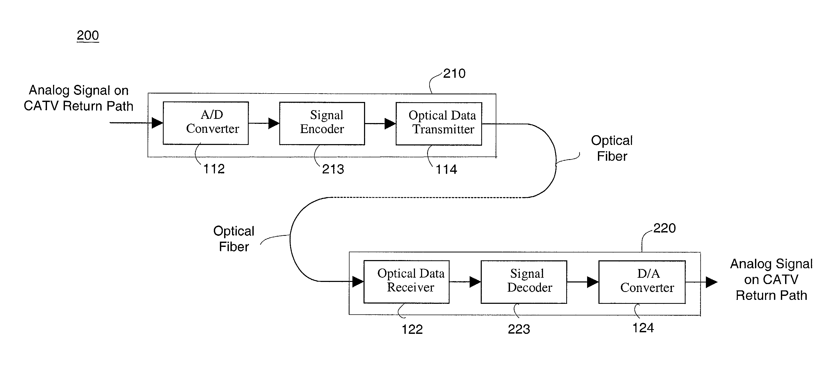
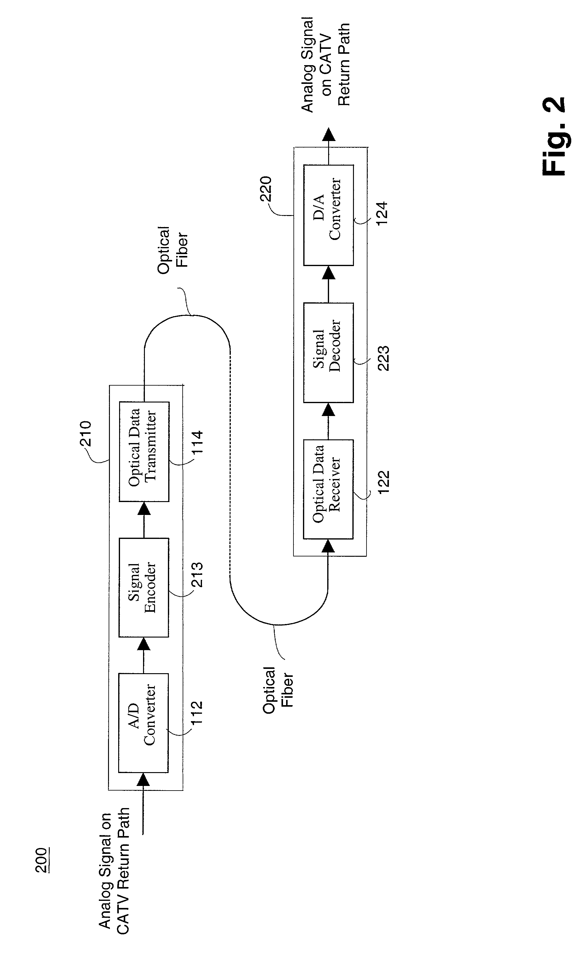
[0023]FIG. 2 is a block diagram depicting a CATV return path 200 according to one embodiment of the present invention. At the CATV return path transmitter 210, a signal encoder 213 is coupled to receive and encode the data signal output of the A / D converter 112. The encoded data signal (output by the encoder 213) is provided to the optical transmitter 114 for transmission to a hub 220. At the hub 220, the signal receiver 122 recovers and generates a local replica of the encoded data signal, and a signal decoder 223 is coupled to receive and decode the encoded data signal. The output of the decoder 223, which is a decoded data signal, is provided to a D / A converter 124 for conversion into analog signals. In this embodiment, the signal encoder 213 and signal decoder 223 allow digital data to be transmitted across the optical link at a lower rate than N*F bits per second (where N is the number of bits and F is the sampling frequency of the A / D converter 112) without significant loss of...


PUM


Abstract

An efficient means for transmitting digitized return path signals over a cable television return path is disclosed. In one embodiment of the invention, the cable television return path includes a node that receives an analog return signal from a subtree of the cable television system and generates a digital transport signal representative of the analog return path signal. The digital transport signal, however, is not a digitized form of the analog return signal. Rather, the digital transport signal is encoded such that fewer bits are used to represent the analog return signal without substantially impacting the accuracy and dynamic range of the signal. At the hub, the digital transport signal is decoded and converted to produce an analog signal that is a close approximation of the analog return signal.

Description

[0001]The present application claims priority to, under 35 U.S.C. 119(e), U.S. Provisional Patent Application bearing 60 / 356,955, filed Feb. 12, 2002, which is incorporated herein by reference.BRIEF DESCRIPTION OF THE INVENTION[0002]The present invention is related generally to upstream data communications over networks primarily designed for downstream transmission of television and data signals. More specifically, the present invention pertains to a device and method for improving performance of digital return path links for a cable television (CATV) hybrid fiber co-axial cable (coax) system.BACKGROUND OF THE INVENTION[0003]Cable television systems (CATV) were initially deployed so that remotely located communities were allowed to place a receiver on a hilltop and then use coaxial cable and amplifiers to distribute received signals down to the town which otherwise had poor signal reception. These early systems brought the signal down from the antennas to a “head end” and then dist...

Claims


Application Information

Patent Timeline
Patent Type & Authority Patents(United States)
IPC IPC(8): H04B10/12H04N7/173
CPCH04N7/17309H04N21/437H04N21/6168
Inventor SAGE, GERALD F.
Owner II VI DELAWARE INC
Why Eureka
Try Eureka