Peripheral compensation system and method of pixel matrix and display system

A pixel matrix, peripheral compensation technology, applied in static indicators, instruments, etc., can solve the problems of threshold voltage drift, driving transistor and organic light emitting diode threshold voltage drift, non-uniformity, etc., to increase the refresh frequency, structure retention, structure simple effect

Active Publication Date: 2015-11-04
PEKING UNIV SHENZHEN GRADUATE SCHOOL
View PDF12 Cites 35 Cited by
  • Summary
  • Abstract
  • Description
  • Claims
  • Application Information

AI Technical Summary

Problems solved by technology

[0006] The structure circuit of the two thin film field effect transistors of the pixel unit driven by the active matrix above is simple, but as time goes by, the components in it will age, especially the drive transistor and the organic light emitting diode will age, directly The consequence is that the threshold voltages of the driving transistor and the organic light-emitting diode will drift, and the threshold voltage drift of the driving transistor and the organic light-emitting diode in each pixel unit in the pixel matrix is ​​also different; made, which will lead to the threshold voltage V of the driving transistor of each pixel unit in the pixel matrix TH It has the characteristics of non-uniformity; in the above two cases, according to the formula (1), it can be seen that the driving current I DS At this time, it will change, which will cause the inhomogeneity of the pixel matrix display
[0007] Aiming at the problem of non-uniform pixel matrix display caused by threshold voltage drift and non-uniformity of driving transistors and organic light-emitting diodes, there are currently two types of threshold voltage compensation methods: pixel unit internal compensation and peripheral compensation
Compensation within the pixel unit is to provide a constant driving current for the organic light-emitting diode through a complex pixel unit circuit structure. In comparison, a simpler pixel unit structure can be used, so it is more suitable for industrial applications

Method used


Image

  • Peripheral compensation system and method of pixel matrix and display system
  • Peripheral compensation system and method of pixel matrix and display system
  • Peripheral compensation system and method of pixel matrix and display system

Examples


Embodiment 1

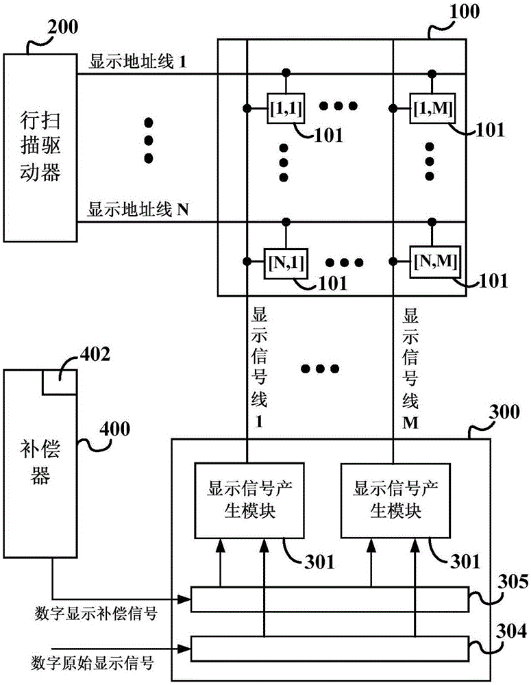
[0035] In one example, please refer to figure 1 , the present embodiment is a display system, including a pixel matrix 100 and a peripheral compensation system of the pixel matrix 100 (hereinafter referred to as the peripheral compensation system).

[0036] The pixel matrix 100 includes N rows and M columns of pixel units 101, N rows of display address lines and M columns of display signal lines. The pixel units 101 are respectively connected to their respective display address lines and display signal lines. Both N and M are positive integers. figure 1 Only 4 pixel units are drawn as an example, respectively at the position [1,1] is the first row and the first column, [N,1] is the Nth row and the first column, [1,M] is the first row and the M Column, and [N,M] is row N and column M.

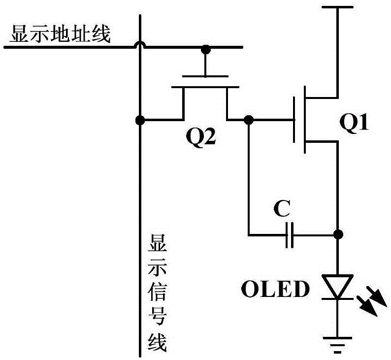
[0037] The pixel unit 101 has various circuits, one of which can be figure 2 The circuit in, which includes a driving transistor Q1, a display switching transistor Q2, a storage capacitor C a...

Embodiment 2

[0050] This embodiment discloses a peripheral compensation system.

[0051] In order to further improve the accuracy of the analog display signal, the column driver 300 in this embodiment also sends an analog correction signal to the pixel matrix 100, and the pixel matrix 100 sends a feedback signal to update the compensation information stored in the compensator 400, and then according to A digital display compensation signal is calculated from the compensation information, and the digital display compensation signal calculated through the updated compensation information is more accurate than the digital display compensation signal in the first embodiment.

[0052] Please refer to Figure 6 , the display system in this embodiment includes a pixel matrix 100 and a peripheral compensation system of the pixel matrix 100 .

[0053]The pixel matrix 100 includes N rows and M columns of pixel units 101, N rows of display address lines, N rows of correction address lines, N rows of...

Embodiment 3

[0111] This embodiment discloses a peripheral compensation system.

[0112] In order to simplify the wiring of the display system and the peripheral compensation system in the first and second implementations and reduce the driver chip area, the correction address signal and the display address signal can be time-multiplexed with the display address line of the row scan driver 200, the analog correction signal and the analog The display signal is time-division multiplexed to the display signal lines of the column driver 300 .

[0113] Please refer to Figure 10 , in this embodiment, the row scan driver 200 sends correction address signals or display address signals to the display address lines in time-division, and the column driver 300 sends analog correction signals and analog display signals to the display signal lines in time-division.

[0114] Please refer to Figure 11 , are two circuit structures of the pixel unit 101 in this embodiment.

[0115] Such as Figure 11 ...


PUM


Abstract

The invention provides a peripheral compensation system and method of a pixel matrix and a display system. The peripheral compensation system includes a row scanning driver (200), a compensator (400) and a column driver (300), wherein the column driver (300) includes a display signal generation module (301), and the display signal generation module (301) includes a first digital-to-analog conversion module (311) having a gamma correction function, a second digital-to-analog conversion module (312) and a first analog addition module (313). While performing precise gamma correction on a digital original signal, the peripheral compensation system is simple in structure, and the number of bits of the first digital-to-analog conversion module is small; and the peripheral compensation system can also perform correction operation during display of a display system, thereby greatly increasing the refreshing frequency of compensation information.

Description

technical field [0001] The present application relates to the field of display technology, in particular to a peripheral compensation system, method and display system of a pixel matrix. Background technique [0002] Due to the advantages of high brightness, high luminous efficiency, wide viewing angle and low power consumption, Organic Light-Emitting Diode (OLED) has been extensively studied in recent years and has been rapidly applied to a new generation of display systems. There are two driving methods of organic light emitting diodes: passive matrix driving (Passive Matrix OLED, PMOLED) and active matrix driving (Active Matrix OLED, AMOLED). Although the cost of the passive matrix driving method is low, it cannot realize high-resolution display because of the phenomenon of crosstalk. In addition, the passive matrix driving current is large, which will reduce the service life of the organic light emitting diode. In contrast, the active matrix driving method is to set a d...

Claims


Application Information

Patent Timeline
Patent Type & Authority Applications(China)
IPC IPC(8): G09G3/32
CPCG09G3/32G09G3/3233
Inventor 林兴武张盛东冷传利王翠翠孟雪张敏
Owner PEKING UNIV SHENZHEN GRADUATE SCHOOL
Why Eureka
Try Eureka