System and Method for Controlling System

a control system and system technology, applied in adaptive control, instruments, computing, etc., can solve the problems of reducing the accuracy of the controller can drop below the required accuracy threshold, and the quantization also reduces the accuracy of the controller on-line execution, so as to reduce the precision of quantized data and achieve greater precision. , the effect of excessive target accuracy

Inactive Publication Date: 2016-08-25
MITSUBISHI ELECTRIC RES LAB INC
View PDF6 Cites 33 Cited by
  • Summary
  • Abstract
  • Description
  • Claims
  • Application Information

AI Technical Summary

Benefits of technology

[0013]It is therefore desired to reduce the precision of the quantized data for on-line execution of the controller, such that the quantized control with quantized data deviates from the true control with true data within predetermined bounds, wherein a precision of the data is defined by a number of bits storing the data in the memory. It is beneficial to have the data stored in the memory with different precisions, wherein the data larger affecting the accuracy of the controller are stored with a greater precision, compared to the data less affecting the accuracy of the controller.
[0014]Some embodiments determine the target accuracy of the controller based on an accuracy of a sensor for sensing, or an estimator for estimating, the current state of the system. This is beneficial because the excessive target accuracy can make controller design more difficult and unnecessary increase the costs of the controller hardware needed to control rapidly changing systems.

Problems solved by technology

For on-line execution, the data have to be stored in the hardware of the controller with potentially low available memory having small numbers of bits for every number stored and processed.
However, the quantization also reduces the accuracy of the on-line execution of the controller as compared with the accuracy of the controller operations with the true precision.
For example, if the selected precision is too small, then the accuracy of the controller can drop below the required accuracy threshold, leading to system malfunctions or even failures.
If the selected precision is too small in the EMPC controller, then the EMPC controller can fail to accurately determine the region for the current state of the controlled system, and, thus can fail to determine the true control for the given current state.

Method used


Image

  • System and Method for Controlling System
  • System and Method for Controlling System
  • System and Method for Controlling System

Examples


Embodiment Construction

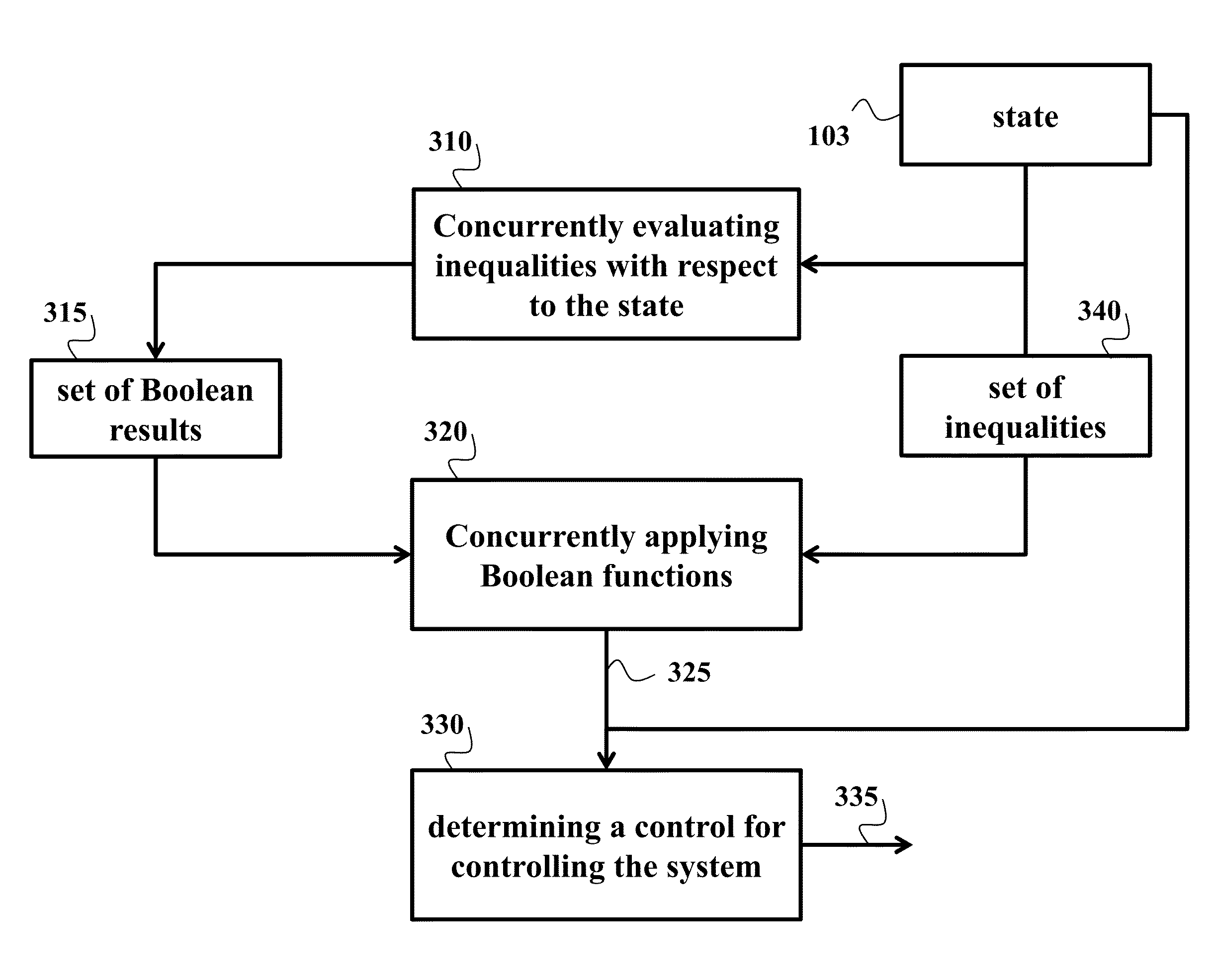
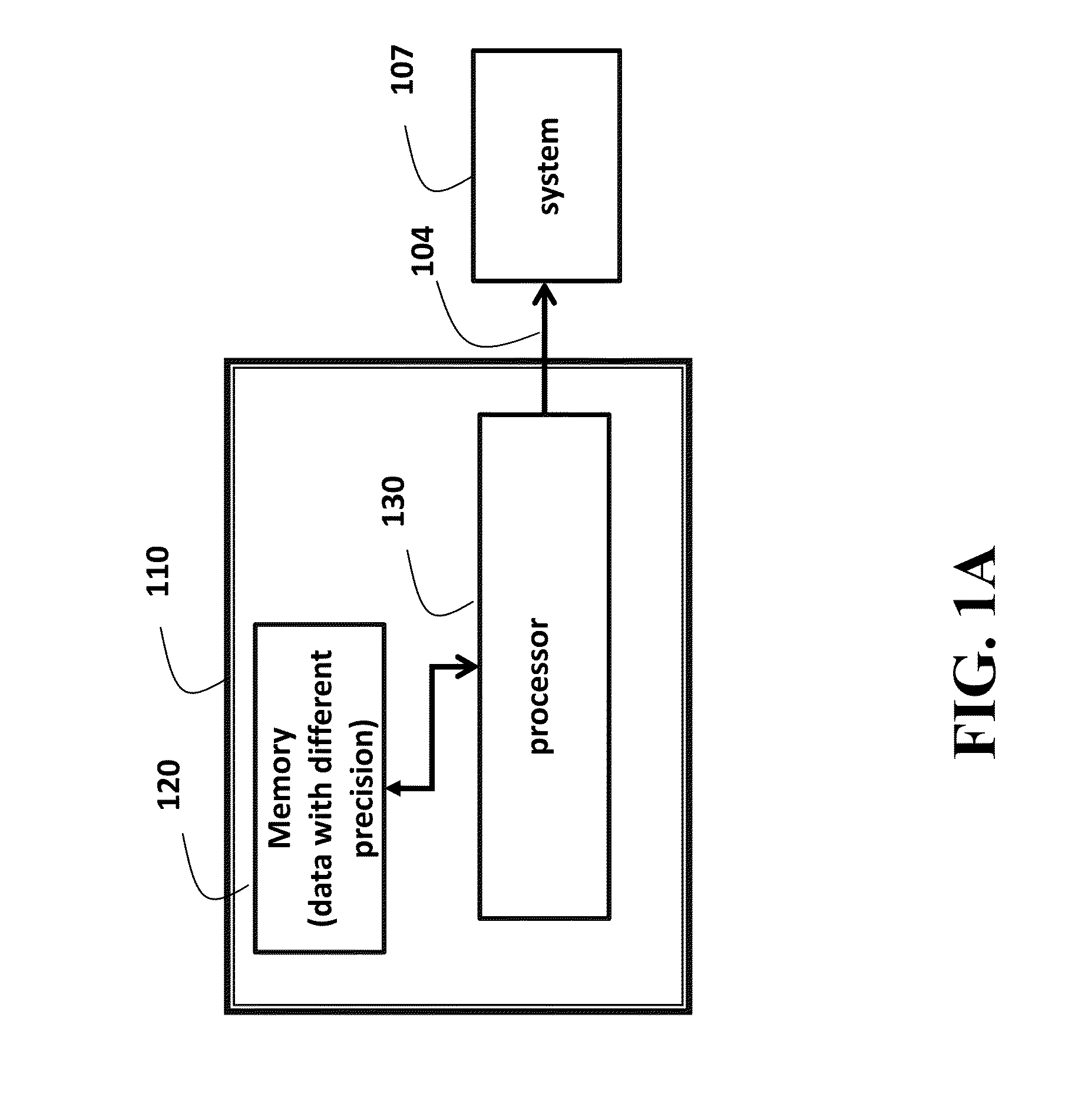
[0044]FIG. 1A shows a block diagram of a controller 110 for controlling a system 107 according to some embodiments of the invention. The controller includes at least one processor 130 for executing modules of the controller. The processor 130 is operatively connected to a non-transitory computer-readable memory 120 storing data for an operation and a control of the system. It is an objective of some embodiments of the invention to determine the control signal 104 transitioning a state of the system from a current state to a next state.

[0045]In some embodiments of the invention, at least two instances of the data are stored in the memory 120 with different precisions, wherein a precision of an instance is defined by a number of bits storing the instance in the memory, such that the processor 130 determines the control 140 using the instances of the data with the different precisions.

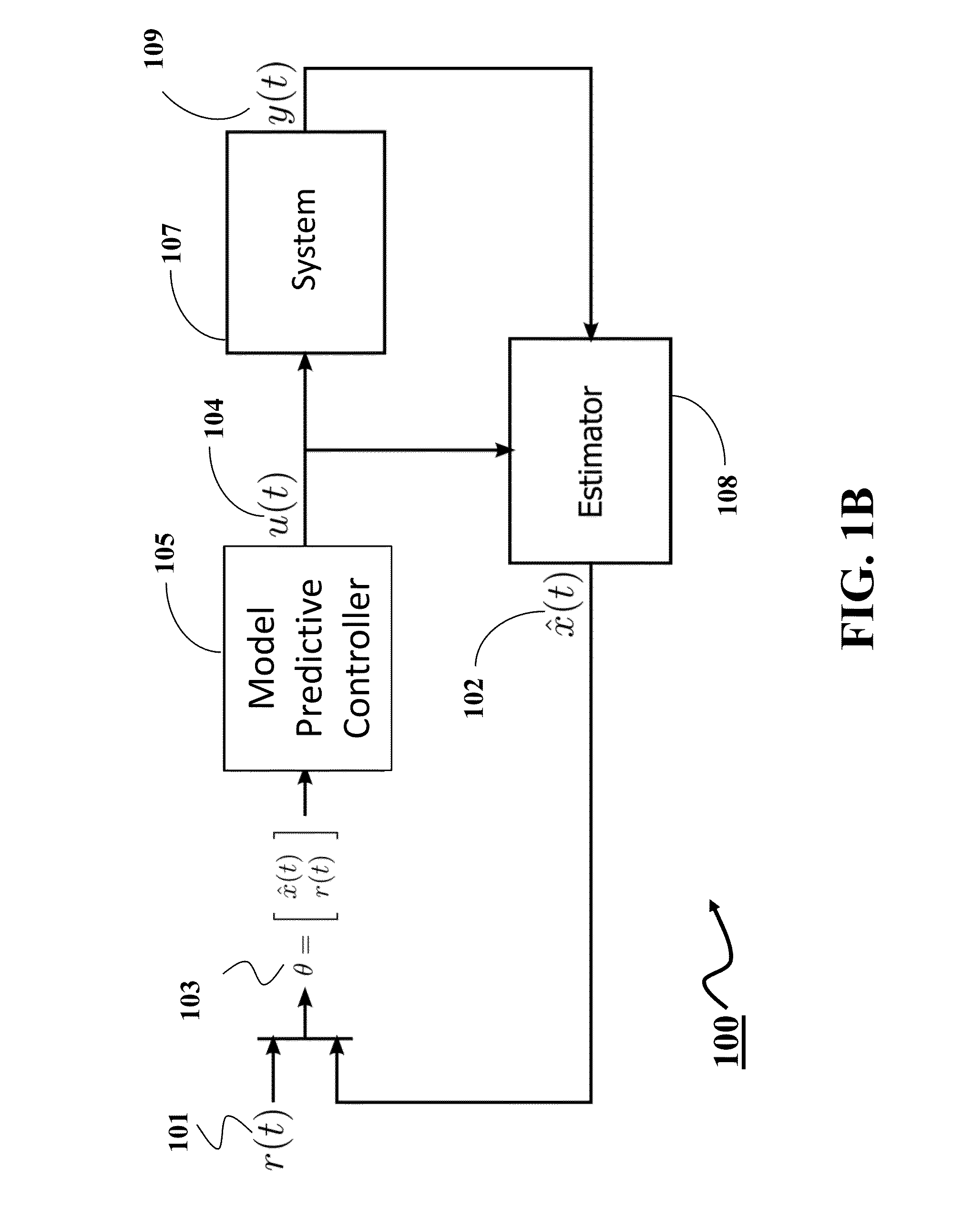
[0046]FIG. 1B shows a block diagram of the control system 100 according to embodiments employing a mod...


PUM


Abstract

A controller for controlling a system includes a non-transitory computer-readable memory storing data for an operation and a control of the system and at least one processor operatively connected to the memory for determining a control signal transitioning a state of the system from a current state to a next state. At least two instances of the data are stored in the memory with different precisions defined by numbers of bits storing the instance in the memory. The processor determines the control signal using the instances of the data with the different precisions.

Description

FIELD OF THE INVENTION[0001]This invention relates generally to controlling an operation of a system, and more particularly to controlling the operation using data stored in a memory of a controller.BACKGROUND OF THE INVENTION[0002]A controller is a device, or set of devices, that manages, commands, directs or regulates the behavior of other devices or systems. Typically, a controller stores data indicative of the operation of the controlled system and use such data for the controlling.[0003]Many advanced control techniques are formulated as optimization problems, which can be solved by programming. For example, one class of such techniques is optimization-based receding time horizon control, such as model predictive control (MPC). There are MPC formulations for both linear and non-linear systems. Non-linear MPC solves non-linear programs in real-time, which can be a challenging task due to limited computing resources, the complexity of the problem to solve, or the time available to...

Claims


Application Information

Patent Timeline
Patent Type & Authority Applications(United States)
IPC IPC(8): G05B13/04
CPCG05B13/048G06F9/30014G06F9/30025H04N19/124H04N19/132
Inventor KNIAZEV, ANDREIZHU, PEIZHENDI CAIRANO, STEFANO
Owner MITSUBISHI ELECTRIC RES LAB INC
Why Eureka
Try Eureka