
Method and apparatus for extending locating range of binocular camera

A binocular camera and positioning range technology, which is applied to the parts of the TV system, TV, electrical components, etc., can solve the problems of loss of positioning accuracy, binocular cameras cannot achieve positioning, and imaging distortion becomes large, so as to avoid frequent rotation Effect

Active Publication Date: 2016-10-26
BEIJING PICO TECH
View PDF4 Cites 9 Cited by
  • Summary
  • Abstract
  • Description
  • Claims
  • Application Information

AI Technical Summary

Problems solved by technology

At present, binocular cameras are usually used for positioning of virtual reality systems. The binocular cameras have a fixed FOV (Field Of View, field of view), and the space for positioning is fixed. Once the user moves to the field of view of the binocular camera Outside the coverage area, the binocular camera will not be able to achieve positioning, thus limiting the range of free movement of the user when using the virtual reality system
[0004] Existing solutions to expand the positioning range of binocular cameras generally increase the space for positioning by increasing the FOV of binocular cameras, but the increase in FOV of binocular cameras will lead to problems such as larger imaging distortion and lower resolution. Loss of positioning accuracy

Method used


Image

  • Method and apparatus for extending locating range of binocular camera
  • Method and apparatus for extending locating range of binocular camera
  • Method and apparatus for extending locating range of binocular camera

Examples


Embodiment Construction

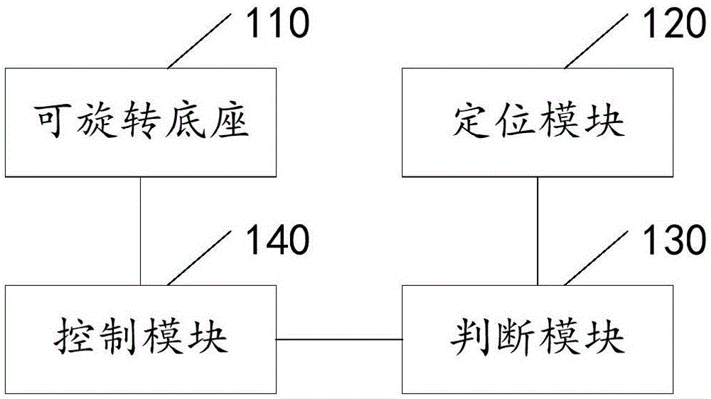
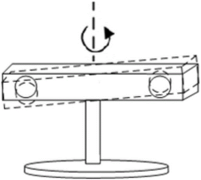
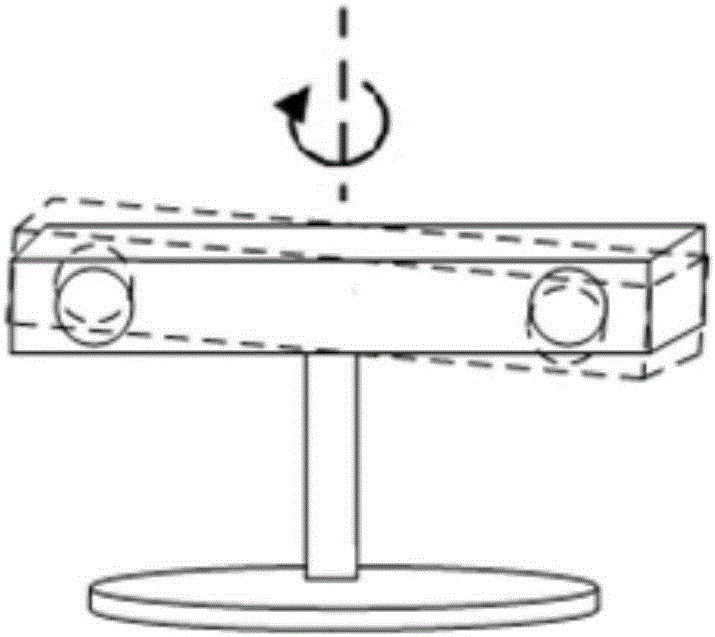
[0045] The design concept of the present invention is: use the binocular camera to track the target to be positioned in real time, and when the target to be positioned is about to exceed the field of view of the binocular camera, adjust the direction of the lens of the binocular camera so that the field of view of the binocular camera always covers the field of view to be determined Target, so that without changing the original FOV of the binocular camera, the positioning range of the binocular camera can be expanded without loss of positioning accuracy.

[0046]In order to make the object, technical solution and advantages of the present invention clearer, the implementation manner of the present invention will be further described in detail below in conjunction with the accompanying drawings.

[0047] figure 1 It is a schematic structural diagram of a device for expanding the positioning range of a binocular camera provided by an embodiment of the present invention. Such as...


PUM


Abstract

The invention discloses a method and an apparatus for extending a locating range of a binocular camera. The apparatus comprises a rotatable pedestal, a locating module, a judging module and a control module; the rotatable pedestal is arranged on the binocular camera, and is used for driving a lens of the binocular camera to rotate; the locating module is used for calculating space coordinates of a to-be-located target in a field of view of the binocular camera in real time according to images of the to-be-located target acquired by the binocular camera; the judging module is used for judging whether the to-be-located target is going to exceed the field of view of the binocular camera according to the space coordinates; the control module is used for controlling the rotatable pedestal to drive the lens of the binocular camera to rotate when the judging module judges that the to-be-located target is going to exceed the field of view of the binocular camera, regulating direction of the lens of the binocular camera, and making the field of view of the binocular camera always cover the to-be-located target. Thus, extension of the locating range of the binocular camera is realized without increase of FOV (Field of View) of the binocular camera and loss of locating accuracy.

Description

technical field [0001] The invention relates to the technical field of binocular stereo vision, in particular to a method and a device for expanding the positioning range of a binocular camera. Background technique [0002] Binocular stereo vision is to simulate the principle of human vision, observe an object from two or more points, obtain images under different viewing angles, and calculate the offset between pixels through the principle of triangulation according to the matching relationship between pixels in the images to obtain the three-dimensional information of the object. [0003] With the development of virtual reality technology, consumers continue to put forward new demands for human-computer interaction interfaces. Using binocular stereo vision technology for positioning can realize the coordinate transformation between the real space and the virtual game space. At present, binocular cameras are usually used for positioning of virtual reality systems. The bin...

Claims


Application Information

Patent Timeline
Patent Type & Authority Applications(China)
IPC IPC(8): H04N13/02
CPCH04N13/296H04N13/239H04N23/695H04N23/45H04N23/69
Inventor 舒玉龙马金波韩玉才
Owner BEIJING PICO TECH
Learn More