
Drawer type UPS power board fan heat dissipation system

A cooling system and drawer-type technology, applied in the field of drawer-type UPS power board fan cooling system, can solve problems such as poor cooling, and achieve the effect of maintaining temperature and avoiding local high temperature problems.

Active Publication Date: 2016-10-26
STATE GRID CORP OF CHINA +2
View PDF3 Cites 0 Cited by
  • Summary
  • Abstract
  • Description
  • Claims
  • Application Information

AI Technical Summary

Problems solved by technology

[0005] The present invention aims at the technical problem of poor refrigeration in the current industrial control machines, and provides a safe and reliable drawer-type UPS power board fan cooling system with low manufacturing and use costs, which can be used for cooling large or small industrial control system equipment

Method used


Image

  • Drawer type UPS power board fan heat dissipation system
  • Drawer type UPS power board fan heat dissipation system

Examples


Embodiment 1

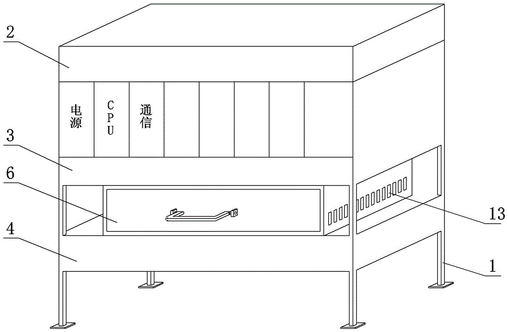
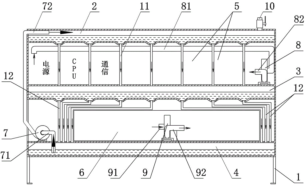
[0018] Embodiment 1: as figure 1 In the drawer-type UPS power board fan cooling system, an upper water tank 2 , a middle water tank 3 and a lower water tank 4 are sequentially arranged on the bracket 1 from top to bottom.

[0019] Between the upper water tank 2 and the lower water tank 4 there are multiple rows of parallel upper layer heat exchange tubes 11 vertically distributed, between the middle water tank 3 and the lower water tank 4 vertically distributed multiple rows of parallel lower layer heat exchange tubes 12 .

[0020] A closed industrial computer installation room 5 is provided between the upper water tank 2 and the lower water tank 4 , and the upper layer heat exchange tubes 11 are distributed in the industrial computer installation room 5 .

[0021] An internal fan 8 is installed in the installation room 5 of the industrial computer to fully circulate the air in the closed room to form an internal air circulation. The air inlet pipe of the internal circulation...

Embodiment 2

[0028] Embodiment 2: On the basis of Embodiment 1, the industrial computer installation room 5 is divided into a plurality of independent chambers, and a plurality of air inlet pipes of the internal circulation fan are respectively located at the top of each independent chamber, and a plurality of air outlet pipes are respectively located in each independent chamber. Separate room bottom.

Embodiment 3

[0029] Embodiment 3: On the basis of Embodiment 1, cooling fins are provided on the outside of the upper heat exchange tube or the lower heat exchange tube.


PUM


Abstract

The invention discloses a drawer type UPS power board fan heat dissipation system. An upper water tank, a middle water tank and a lower water tank are arranged on a bracket from top to bottom in sequence. Upper layer heat exchange tubes are vertically distributed between the upper water tank and the lower water tank. Lower layer heat exchange tubes are vertically distributed between the middle water tank and the lower water tank. The upper layer heat exchange tubes are distributed in an industrial personal computer mounting chamber. Moreover, airflow inner circulation is arranged in the industrial personal computer mounting chamber. The lower layer heat exchange tubes are distributed out of a drawer in a drawer type fan chamber. Air flow outer circulation is arranged in the drawer type fan chamber. A water inlet tube of a water pump is communicated with the lower water tank. The water outlet tube of the water pump is communicated with the upper water tank, thereby forming water circulation. According to the system, cooling to the industrial personal computer mounting chamber belongs to fully sealed cooling; therefore, industrial personal computers can be avoided from contacting with an outdoor environment; and the internal parts of the industrial personal computers can be avoided from being influenced by the outdoor environment. A water circulation system, an inner airflow circulation system and an outer airflow circulation system are arranged. The three circulation systems match with each other.

Description

Technical field: [0001] The invention belongs to the technical field of cooling of core equipment of an industrial control system in water conservancy projects, and in particular relates to a drawer-type UPS power board fan cooling system. Background technique: [0002] Industrial computer is the core equipment commonly used in industrial control systems. Some industrial computer bodies are not equipped with cooling fans, but only have heat sinks. Operation at high temperatures can cause degraded equipment performance and shortened service life. [0003] A cooling fan is installed in the installation room of some industrial computers, and the cooling fan is used to realize the exchange of internal and external airflow to achieve the purpose of heat exchange. However, since the industrial control computer is the core equipment of the system, long-term internal and external airflow will introduce external unfavorable factors into the industrial control system. A common proble...

Claims


Application Information

Patent Timeline
IPC IPC(8): H05K7/20
CPCH05K7/20909
Inventor 刘鹏龙张红方师敬民马聖恒张旭代晓马亚楠
Owner STATE GRID CORP OF CHINA
Learn More