
A device and blind insertion method for remote sensing camera multi-chip ccd device blind insertion

A remote sensing camera, CCD7 technology, applied in the field of optical remote sensors, can solve problems such as affecting insertion, breaking, pin or pin bending, etc., to reduce pin damage, prevent damage and deformation, and facilitate debugging.

Active Publication Date: 2019-03-26
BEIJING RES INST OF SPATIAL MECHANICAL & ELECTRICAL TECH
View PDF4 Cites 0 Cited by
  • Summary
  • Abstract
  • Description
  • Claims
  • Application Information

AI Technical Summary

Problems solved by technology

[0003] The existing CCD device insertion technology generally has only one CCD device on one plane, and the device pins are only about 50 pins in two rows. CCD device mating completed
However, after optical splicing of CCD devices, the deformation of the pins and the deformation of the extended pins affect the insertion of the electronic assembly process. Generally, the blind insertion of multiple CCD devices in a plane is difficult to detect with the naked eye. The circuit board and multi-chip CCD devices are mated, and the printed circuit board assembly and multi-chip CCD devices with hundreds of pins are one-time blind plug-in. At present, there is a lack of reliable means, and the efficiency in the assembly process is low. Very low, and it is very easy to bend or even break the pins or pins, causing heavy economic losses

Method used


Image

  • A device and blind insertion method for remote sensing camera multi-chip ccd device blind insertion
  • A device and blind insertion method for remote sensing camera multi-chip ccd device blind insertion
  • A device and blind insertion method for remote sensing camera multi-chip ccd device blind insertion

Examples


Embodiment Construction

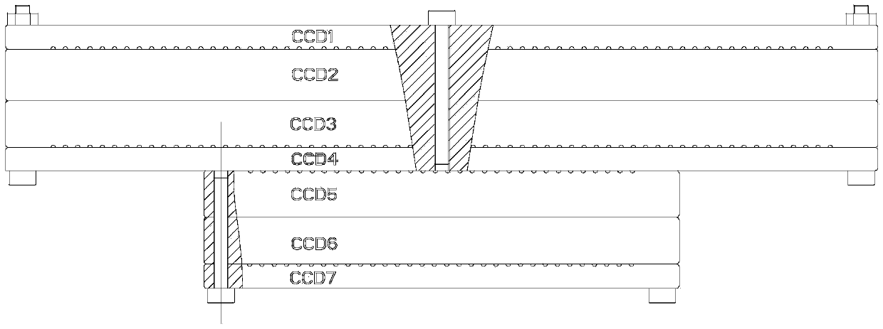
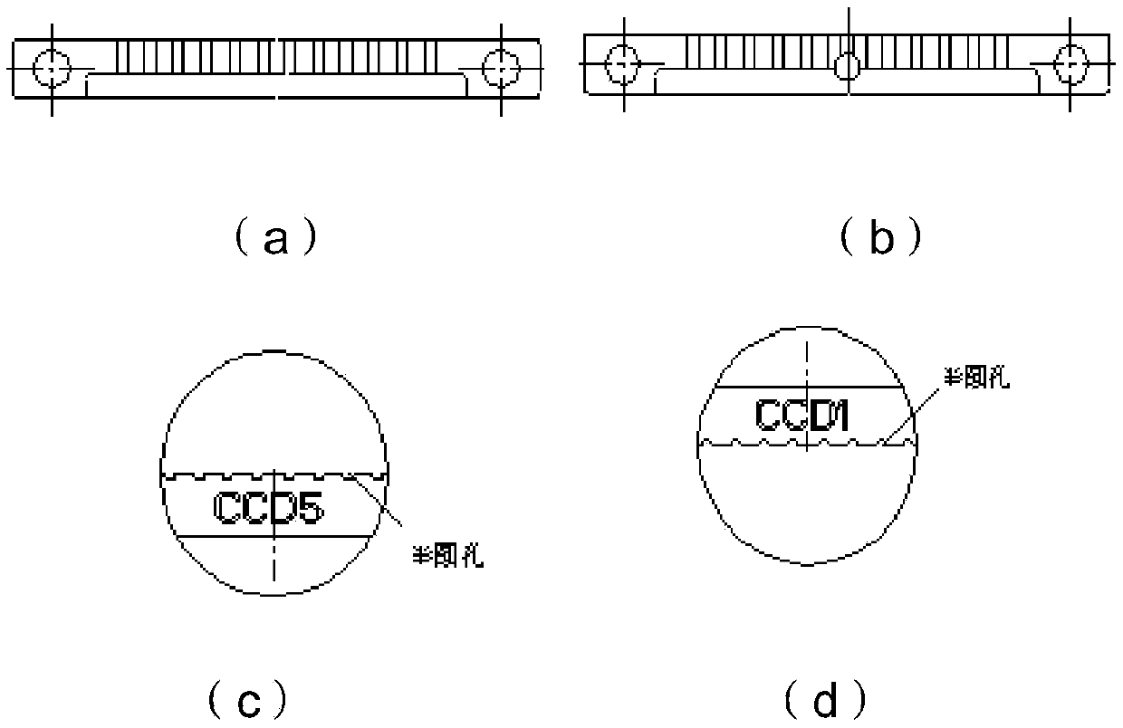
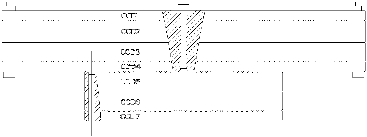
[0033] like figure 1 As shown, the CCD pin calibration tool is used to correct and accurately fix the pins of the CCD device 2 to ensure that the pins are perpendicular to the body of the CCD device 2 without deformation. Because the 2 pins of the CCD device are soft, the clamping is easy to deform, and after the extended pins are installed, there is little visual space for the operator to observe the 2 pins of the CCD device due to the blocking of the pin base of the CCD device 2 . At the same time, in order to facilitate adjustment after clamping, the pin clamping place should be easy to observe, so the tooling is made of visible materials. The CCD pin calibration tool adopts the form of half-hole mold clamping to ensure that the diameter of the hole after mold clamping is slightly smaller than the diameter of the device, so that the alignment of the half-hole mold clamping is accurate and not misplaced. The CCD pin calibration tooling consists of 7 tooling calibration hole...


PUM


Abstract

The invention provides a device used for blind insertion of a multi-chip CCD device of a remote sensing camera and a blind insertion method. Positioning matching between a CCD pin of the CCD device (2) and a plated through hole in a printed circuit board (4) is guaranteed by designing a CCD pin correcting tool, a CCD lengthened contact pin correcting tool and printed board correcting templates with different thicknesses and combining steps of the blind insertion method of the multi-chip CCD device (2) of a remote sensing camera. According to the device and the blind insertion method, one-time blind insertion installation of the printed circuit board and the multi-chip CCD device is realized, and the defect that the pin is bent and broken after blind insertion of the multi-chip CCD device is overcome, so that the installation efficiency is improved, and the economic loss is reduced.

Description

technical field [0001] The invention belongs to the technical field of optical remote sensors, and relates to a device for blind insertion of multiple CCD devices of remote sensing cameras and a method for inserting multiple CCD devices of remote sensing cameras. Background technique [0002] The focal plane assembly of the remote sensing CCD camera is composed of three parts: the focal plane assembly, the focusing mechanism, and the focusing support frame assembly. , bonding, after the implementation of relevant thermal control and mechanical assembly, the one-time blind insertion of printed circuit board assemblies and multiple CCD devices with multiple rows and hundreds of pins is required. [0003] The existing CCD device insertion technology generally has only one CCD device on one plane, and the device pins are only about 50 pins in two rows. The CCD devices are mated and plugged in. However, after optical splicing of CCD devices, the deformation of the pins and the ...

Claims


Application Information

Patent Timeline
Patent Type & Authority Patents(China)
IPC IPC(8): H05K13/04
CPCH05K13/0482
Inventor 徐伟玲杨晶纪春梅王小勇李涛范燕平肖正航
Owner BEIJING RES INST OF SPATIAL MECHANICAL & ELECTRICAL TECH
Learn More