Rotation identification method of camera and electronic equipment with rotation camera

A technology of rotating camera and recognition method, which is applied in the field of camera rotation recognition method and electronic equipment, can solve the problems of multiple flipping, inaccurate recognition, high production process and structure requirements, and achieve flip recognition, simple hardware implementation, and guaranteed The effect of accuracy

Inactive Publication Date: 2017-07-07
SHANGHAI DROI TECH CO LTD
View PDF0 Cites 0 Cited by
  • Summary
  • Abstract
  • Description
  • Claims
  • Application Information

AI Technical Summary

Problems solved by technology

In actual production and use, the magnet on the rotating shaft will be affected by the surrounding environment, and the magnetization phenomenon will gradually fade away. It is very likely that there will be misoperation, resulting in inaccurate recognition
Moreover, the production requirements of the magnet are relatively high, and the magnetic field strengt

Method used


Image

  • Rotation identification method of camera and electronic equipment with rotation camera
  • Rotation identification method of camera and electronic equipment with rotation camera
  • Rotation identification method of camera and electronic equipment with rotation camera

Examples


Embodiment Construction

[0036] In order to make the object, technical solution and advantages of the present invention clearer, various embodiments of the present invention will be described in detail below in conjunction with the accompanying drawings. However, those of ordinary skill in the art can understand that, in each implementation manner of the present invention, many technical details are provided for readers to better understand the present application. However, even without these technical details and various changes and modifications based on the following implementation modes, the technical solution claimed in each claim of the present application can be realized.

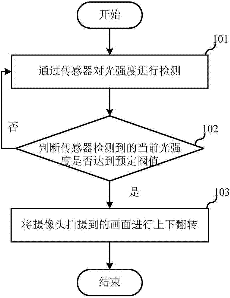
[0037] In an embodiment of the present invention, the camera and the sensor are installed on the rotating body, the sensor can be placed on the rotating shaft of the rotating body (it can be on the side, above or below), and the camera and the sensor are respectively located on two opposite sides of the rotating body. On the...


PUM


Abstract

The invention relates to the electronic technology field and discloses a rotation identification method of a camera and electronic equipment with a rotation camera. In the invention, a sensor installed on a rotation body is used; through real-time detection of light intensity, a current rotation position of the rotation body is acquired; and then according to the detected current rotation position of the rotation body, a frame shot by the camera is overturned up and down. The camera is located on the rotation body, and rotation of the rotation body drives rotation of the camera. By using the rotation identification method of the camera, stability of camera rotation identification can be effectively increased; and the structure of the equipment is simple, installation is easy to achieve and cost is saved.

Description

technical field [0001] The invention relates to the field of electronic technology, in particular to a camera rotation identification method and electronic equipment. Background technique [0002] With the development of electronic technology, the camera on many electronic devices can realize the rotation function. Most of the current rotating cameras use Hall sensors and magnets on the rotating shaft to realize the flip recognition of the camera. In actual production and use, the magnet on the rotating shaft will be affected by the surrounding environment, and the magnetization phenomenon will gradually fade away. Misoperation is likely to occur, resulting in inaccurate identification. Moreover, the production requirements of the magnet are relatively high, and the magnetic field strength above the Hall must meet the minimum standard for Hall sensor induction, and the consistency of the magnet is difficult to guarantee. [0003] In addition, the two materials (Hall and mag...

Claims


Application Information

Patent Timeline
IPC IPC(8): H04N5/232G01B11/00
CPCG01B11/00H04N23/66
Inventor 沈永庆
Owner SHANGHAI DROI TECH CO LTD
Why Eureka
Try Eureka