
Extension-type winder applicable to electric wires and processing technique of extension-type winder

A wire and cable and processing technology, applied in the field of retractable wire winder and its processing technology, can solve the problems of waste of wire winder, messy desktop, heat collection of wires, etc. The effect of improving the tightness of the connection

Active Publication Date: 2016-11-02
TAICANG LINYUAN CABLES & CORDS CO LTD
View PDF7 Cites 1 Cited by
  • Summary
  • Abstract
  • Description
  • Claims
  • Application Information

AI Technical Summary

Problems solved by technology

[0002] With the rapid development of social economy, both enterprise production and people's life are mostly electrified and intelligent, which leads to a lot of wires and cables in workshops, offices and homes. The wires and cables are routed from the wall to reduce the indoor clutter caused by their exposure. However, even so, many connecting wires such as home appliances and computers will still cause clutter on the desktop, and many wires will be entangled. If not The ability to dissipate heat in a timely manner will lead to heat accumulation in the wound wires. At the same time, once some of the wires are damaged or overheated, a magnetic field will be generated around them and affect other wires around them; and, when the wires and cables are wound When going to the winder, because each cable needs to be wound on the winder with different lengths, if the winder is too short, it will not be enough; if it is too long, the wires needed are shorter, so It will lead to the waste phenomenon of the wire winder. In order to solve the above problems well, the applicant provides a retractable wire winder for wire and cable

Method used


Image

  • Extension-type winder applicable to electric wires and processing technique of extension-type winder
  • Extension-type winder applicable to electric wires and processing technique of extension-type winder

Examples


Embodiment 1

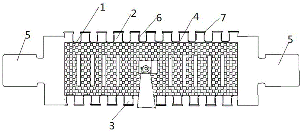
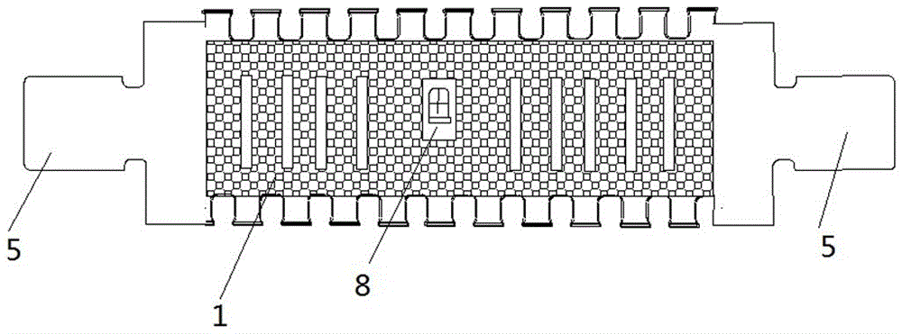
[0035] Such as figure 1 with figure 2 A retractable wire winder for electric wires and cables is shown, comprising: a wire winder body 1, the upper and lower sides of the wire winder body 1 are respectively provided with a first rack 2 and a second rack 3 , the middle part is provided with a perforation 4, and its two ends are provided with clamping strips 5, the surface of the said winder body 1 is concave-convex, and the first rack 2 and the second rack 3 are Lugs 7 are provided on both sides of the teeth, protective sleeves 6 are provided on the first rack 2 and the second rack 3 , and the clamping strip 5 is matched with the through hole 4 .

[0036] The clamping bar 5 described in this embodiment is in a convex shape, and inner grooves are provided on both sides of one end close to the end of the winding body 1 .

[0037] The inside of the protective cover 6 described in this embodiment is concave-convex, and its inner edge is provided with lugs, which cooperate with t...

Embodiment 2

[0042] The structure of the wire winder used in the processing technology of the retractable wire winder in the wire and cable described in this embodiment is the same as that in Embodiment 1.

[0043] Such as figure 1 with figure 2 A retractable wire winder for wires and cables is shown, comprising: a wire winder body 1, the upper and lower sides of the wire winder body 1 are respectively provided with a first rack 2 and a second rack 3 , the middle part is provided with a perforation 4, and its two ends are provided with clip bars 5, the surface of the said winding device body 1 is concave-convex, and the first rack 2 and the second rack 3 are Lugs 7 are provided on both sides of the teeth, protective sleeves 6 are provided on the first rack 2 and the second rack 3 , and the clamping strip 5 is matched with the through hole 4 .

[0044] The clamping bar 5 described in this embodiment is in a convex shape, and inner grooves are provided on both sides of one end close to the ...


PUM


Abstract

The invention discloses an extension-type winder applicable to electric wires. The extension-type winder applicable to electric wires comprises a winder body. A first rack is arranged at the upper edge of the winder body, a second rack is arranged at the lower edge of the winder body, and through holes are formed in the middle of the winder body. Clamping bars are arranged at the two ends of the winder body. The first rack and the second rack are each provided with a protection cover. The clamping bars are matched with the through holes. According to the extension-type winder applicable to electric wires, since the first rack is arranged at the upper edge of the winder body and the second rack is arranged at the lower edge of the winder body, electric wires are well stored and arranged by being evenly wound in grooves in the racks; and meanwhile, the through holes are formed in the middle of the winder body, and the clamping bars are arranged at the two ends of the winder body, when a wire to be wound is short, the redundant part can be wound around the winder body and penetrate through the through holes in proper positions through the clamping bars so that the wound winder body can be fixed, and therefore the winder body can well extend and retract according to actual demands.

Description

technical field [0001] The invention belongs to the field of electric wires and cables, and in particular relates to a retractable winding device used in electric wires and cables and a processing technology thereof. Background technique [0002] With the rapid development of social economy, both enterprise production and people's life are mostly electrified and intelligent, which leads to a lot of wires and cables in workshops, offices and homes. The wires and cables are routed from the wall to reduce the clutter in the room caused by their exposure. However, even so, many connecting wires such as home appliances and computers will still cause clutter on the desktop, and many wires will be entangled. If you do not The ability to dissipate heat in a timely manner will lead to heat accumulation in the wound wires. At the same time, once some of the wires are damaged or overheated, a magnetic field will be generated around them and affect other wires around them; and, when the...

Claims


Application Information

Patent Timeline
IPC IPC(8): B65H75/10B65H75/24B65H75/26
CPCB65H75/10B65H75/241B65H75/265B65H2701/34
Inventor 曹惠忠
Owner TAICANG LINYUAN CABLES & CORDS CO LTD
Learn More