Rotary knob assembly and household electric appliance

A technology for household appliances and knobs, applied in the field of electronic control components, can solve the problem of inconvenient observation of operating parameters of knobs, and achieve the effect of improving user experience and facilitating observation.

Active Publication Date: 2016-11-02
GREE ELECTRIC APPLIANCES INC OF ZHUHAI
View PDF7 Cites 5 Cited by
  • Summary
  • Abstract
  • Description
  • Claims
  • Application Information

AI Technical Summary

Problems solved by technology

[0004] In view of this, the embodiment of the present invention provides a knob assembly and a household appl

Method used


Image

  • Rotary knob assembly and household electric appliance
  • Rotary knob assembly and household electric appliance
  • Rotary knob assembly and household electric appliance

Examples


Example Embodiment

[0037] Example one

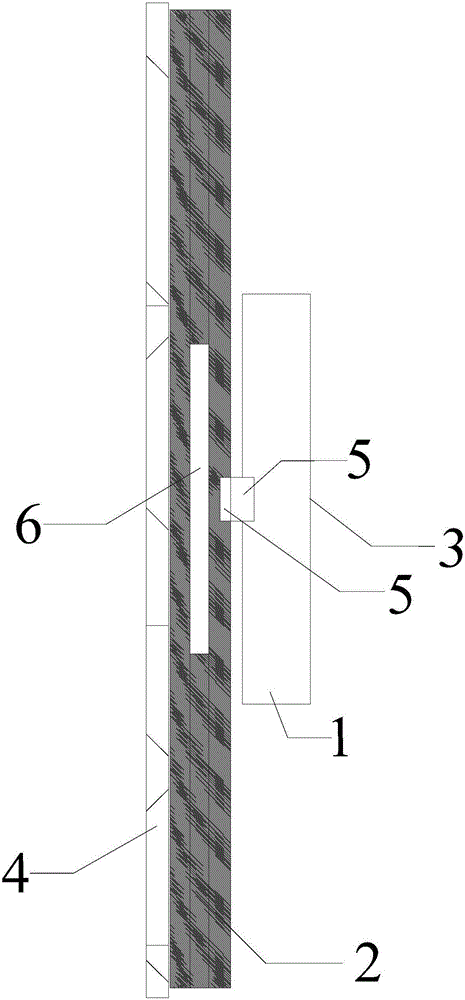
[0038] figure 1 It is a schematic diagram of the structure of the knob assembly provided in the first embodiment of the present invention, see figure 1 , The knob assembly includes: a panel, the panel is fixedly arranged on the mounting surface; a knob, the knob is located on the panel and rotates relative to the panel; a display screen, the display screen is fixedly arranged on the The outer surface of the knob is used to display the image; the rotation state detection device (not shown in the figure) is used to detect the rotation state of the knob; the display control device (not shown in the figure) is used to control the position when the knob is rotated. The display screen displays the display angle of the image.

[0039] Among them, the panel can be designed as a multi-layer structure as required and fixed on the mounting surface. For some appliances, such as TVs, radios, etc., the panel can be embedded on the outer surface of the appliance; for equipme...

Example Embodiment

[0051] Example two

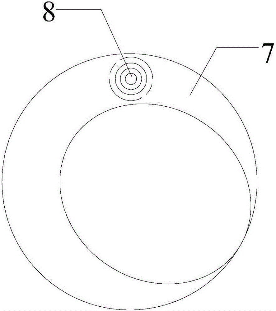
[0052] Figure 4 It is a schematic diagram of the appearance of the knob assembly provided in the second embodiment of the present invention. This embodiment is based on the first embodiment. In this embodiment, the knob assembly includes: a panel, the panel is fixedly arranged on the mounting surface; a knob, the knob is located on the panel and rotates relative to the panel; a display screen, the display screen is fixed Is arranged on the outer surface of the knob and is used to display images; a rotation state detection device (not shown in the figure) is used to detect the rotation state of the knob; a display control device (not shown in the figure) is used to rotate the knob When controlling the display angle of the image displayed on the display screen.

[0053] In this embodiment, the knob is located on the panel and rotates relative to the panel. Illustratively, the knob can be connected to the panel through a connecting rod, and can be rotated relat...


PUM


Abstract

The invention discloses a rotary knob assembly and a household electric appliance. The rotary knob assembly comprises a panel, a rotary knob, a display screen, a rotating state detection device, and a display control device, wherein the panel is fixedly arranged on an installation plane, the rotary knob is positioned on the panel and rotates relative to the panel, the display screen is fixed on an outer surface of the rotary knob and is used for displaying images, the rotating state detection device is used for detecting a rotating state of the rotary knob, and the display control device is used for controlling a display angle of the images displayed by the display screen when the rotary knob rotates; when the rotary knob rotates, a user can observe operation parameters of the rotary knob without going along a rotating direction of the rotary knob, and the user can therefore conveniently observe the operation parameters of the rotary knob; user experience is improved.

Description

Technical field [0001] The present invention relates to the technical field of electronic control components, in particular to a knob assembly and household appliances. Background technique [0002] The knob is a manual element that is turned by hand. According to functional requirements, it can be rotated multiple times continuously, and the rotation angle can reach 360°. It can be rotated or pushed out to start and manipulate or control electrical equipment, such as radios, televisions, or central air conditioners. [0003] When operating the knob, the user obtains the operating parameters of the knob by observing the rotation of an ordinary circular protrusion, disc or dial with one or a series of labels engraved on the edge of the knob. However, with the abundant functions of controlled electrical appliances, a knob that can only display the rotation angle of the knob can no longer meet the needs of users. At present, knobs are configured for some electrical appliances with ...

Claims


Application Information

Patent Timeline
IPC IPC(8): H01H19/02H01H9/16G09G5/00
CPCG09G5/00H01H9/16H01H19/02
Inventor 姚果
Owner GREE ELECTRIC APPLIANCES INC OF ZHUHAI
Why Eureka
Try Eureka