Spray irrigation robot

A technology of robots and racks, applied in the field of robots, can solve the problems of high laying and maintenance costs, easy loss, and difficulty in widespread popularization of sprinkler irrigation equipment, and achieves the effect of reducing laying and maintenance costs and saving water resources.

Inactive Publication Date: 2016-11-09
张学衡
16 Cites 7 Cited by

AI-Extracted Technical Summary

Problems solved by technology

[0002] As water resources become less and less, sprinkler irrigation is becoming more and more important. However, due to the high cost...

Abstract

The invention discloses a spray irrigation robot, comprising a base, a walking mechanism, a water taking device, a control module, a spray irrigation module, a water tank, a first hydraulic cylinder, a support and a power unit. The first hydraulic cylinder is fixedly arranged on the base. The walking mechanism is fixedly arranged on the first hydraulic cylinder through a rack. The water taking device is fixedly arranged on the base through a fixing frame. The control module is fixedly arranged on the base. The spray irrigation module is fixedly arranged on the base through a fixing base. The water tank is fixedly arranged on the base. The power unit is fixedly arranged on the base through the support. By adoption of the spray irrigation robot, water resources can be saved, laying and maintenance cost of irrigation equipment is reduced, and the robot is applicable to various terrains.

Application Domain

Technology Topic

Image

  • Spray irrigation robot
  • Spray irrigation robot
  • Spray irrigation robot

Examples

  • Experimental program(1)

Example Embodiment

[0013] The present invention will be further described below in conjunction with specific embodiments. The illustrative embodiments and description of the present invention are used to explain the present invention, but are not intended to limit the present invention.
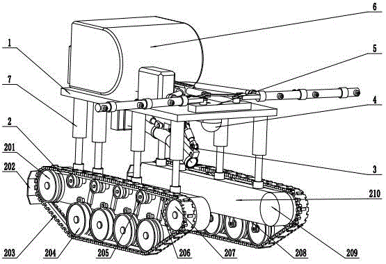
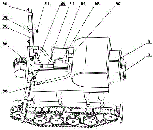
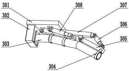
[0014] Such as figure 1 , figure 2 , image 3 As shown, a sprinkler irrigation robot includes a base 1, a group of walking mechanism 2, a water intake device 3, a control module 4, a sprinkler irrigation module 5, a water tank 6, 8 first hydraulic cylinders 7, a support 8, and a power unit 9, which It is characterized in that one end of the eight first hydraulic cylinders 7 is symmetrically installed on the lower bottom surface of the base 1, and the other end is fixedly installed on the upper end surface of the frame 210 of the walking mechanism 2, and the water intake device 3 passes through a fixed frame 304 is fixedly installed on the lower end surface of the base 1, the control module 4 is fixedly installed on the lower end surface of the base 1, the sprinkler irrigation module 5 is fixedly installed on the lower end surface of the base 1 through a fixing seat 504, and the water tank 6 is fixed Installed on the upper end surface of the base 1, and the power unit 9 is fixedly installed on the upper end surface of the base 1 through a bracket 8;
[0015] The 1 set of walking mechanism 2 includes 2 front guide wheels 201, 2 baffles 202, 2 crawlers 203, 8 road wheels 204, 8 guide wheels 205, 8 shock absorption 206, and 2 driving wheels 207 , 8 connecting rods 208, 2 hydraulic motors 209, and 2 frames 210, characterized in that: the two front guide wheels 201 are rotatably mounted on the mounting shafts of the two frames 210, and the two gears The plate 202 is fixedly installed on the front face of the frame 210, and the two ends of the eight shock absorbers 206 and the eight connecting rods 208 are respectively hinged on the mounting shafts of the eight road wheels 204 and the two frames 210. The two hydraulic motors 209 are fixedly installed on the two frames 210, the two driving wheels 207 are fixedly installed on the shafts of the two hydraulic motors 209, and the two crawlers 203 are installed on the two front guide wheels 201, 8. There are two road wheels 204, eight guide wheels 205, and two driving wheels 207;
[0016] The water intake device 3 includes a bottom plate 301, a water pump 302, a water pumping pipe 303, a fixing frame 304, a first support rod 305, a second hydraulic cylinder 306, a second support rod 307, and a third hydraulic cylinder 308, and is characterized by: The water pump 302 is fixedly installed on the lower end surface of the bottom plate 301, the water outlet is connected to the water tank 6 through a pipe, and the water inlet is fixedly connected to one end of the water pumping pipe 303. The water pumping pipe 303 is fixedly installed on the fixing frame 304. The second support rod 307 is hinged to the support of the bottom plate 301, the first support rod 305 is hinged to the second support rod 307, and the fixing frame 304 is fixedly installed on the first support rod 305 and the second support rod 307 In the lower installation groove, the third hydraulic cylinder 308 is hinged on the support of the bottom plate 301 and the second support rod 307, and the second hydraulic cylinder 306 is hinged on the first support rod 305 and the second support rod 307. Bracket
[0017] The sprinkler irrigation module 5 includes 6 nozzles 501, 2 support rods 502, 2 sprinkler pipes 503, fixed seat 504, 2 tie rods 505, 2 hoses 506, connecting pipe 507, tee 508, variable The pump 509, the fourth hydraulic cylinder 510, and two set screws 511 are characterized in that the fourth hydraulic cylinder 510 is fixedly installed on the upper end surface of the fixing base 504, and the two support rods 502 are hinged on the fixing base 504 On the end face mounting shaft, the two tie rods 505 are hinged on the brackets of the two support rods 502 and the fourth hydraulic cylinder 510, and the two water spray pipes 503 are rotatably installed at the ends of the two support rods 502. On the nozzle, the two set screws 511 are installed on the locking blocks on the two support rods 502, the six nozzles 501 are fixedly installed on the two spray pipes 503, and the variable pump 509 It is fixedly installed on the base 1, the connecting pipe 507 is fixedly installed on the water inlet of the variable pump 509 and the water tank 6, one end of the tee 508 is fixedly installed on the water outlet of the variable pump 509, and the hose 506 Both ends are fixedly installed on the other two interfaces of the water inlet of the support rod 502 and the tee 508.
[0018] The working principle of the present invention is: when the present invention is in use, the user first sets the area to be sprinkled in the control module 4, adjusts the angle of the sprinkler pipe 503, and locks it with the set screw 511, and the water intake device 3 is controlled automatically by the hydraulic cylinder The water is taken, and the water is automatically retracted after the water is taken. The sprinkler irrigation module 5 is deployed for sprinkler irrigation. The variable pump 509 controls the sprinkler irrigation water volume.

PUM

no PUM

Description & Claims & Application Information

We can also present the details of the Description, Claims and Application information to help users get a comprehensive understanding of the technical details of the patent, such as background art, summary of invention, brief description of drawings, description of embodiments, and other original content. On the other hand, users can also determine the specific scope of protection of the technology through the list of claims; as well as understand the changes in the life cycle of the technology with the presentation of the patent timeline. Login to view more.

Similar technology patents

Preparation method for methotrexate/layered double hydroxide nanocomposite

InactiveCN102641507AEnergy savingSave waterOrganic active ingredientsAntipyreticDivalent metalPeptization
Owner:江苏顺德缘文化科技股份有限公司

Classification and recommendation of technical efficacy words

Why Eureka
Try Eureka