Guide type plate cutting device

A cutting device and guided technology used in metal processing, smoke removal, cleaning methods and utensils, etc., can solve problems such as sheet cracking and sheet tearing

Inactive Publication Date: 2016-11-09
芜湖昊轩环保新材料有限公司
View PDF11 Cites 4 Cited by
  • Summary
  • Abstract
  • Description
  • Claims
  • Application Information

AI Technical Summary

Problems solved by technology

The existing plate cutting device generally cuts the plate directly with the cutter head moving from top to bottom. Due to the effect ...

Method used


Image

  • Guide type plate cutting device
  • Guide type plate cutting device

Examples


Embodiment Construction

[0032] Specific embodiments of the present invention will be described in detail below in conjunction with the accompanying drawings. It should be understood that the specific embodiments described here are only used to illustrate and explain the present invention, and are not intended to limit the present invention.

[0033] In the present invention, in the absence of a contrary statement, the orientation words included in the term, such as "upper, lower, inner, outer, top, bottom", etc., only represent the orientation of the term in the normal use state, or for the purpose of A common term understood by those skilled in the art, and should not be considered as a limitation of the term.

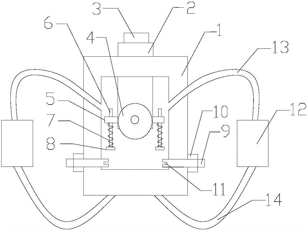
[0034] The invention provides a guided plate cutting device, such as figure 1 As shown, it includes a main body 1, a cutting cavity is formed in the main body 1 along the conveying direction of the plate, the bottom of the cutting cavity is formed with a cutting groove downward along the ve...


PUM


Abstract

The invention discloses a guide type plate cutting device which comprises a main body. A cutting cavity is formed in the main body in the conveying direction of a plate. The bottom of the cutting cavity is provided with a cutting groove downwards in the vertical direction. The top of the main body is provided with a tool bit assembly for fixing a tool bit, and the tool bit assembly can move in the vertical direction so that the tool bit can extend into the cutting cavity. The bottoms of the two ends of the tool bit assembly horizontally extend outwards to form lugs. Each lug is provided with a through hole which extends vertically, a guide rod is arranged in each through hole, the bottom of each guide rod is provided with a pressing block, and a compressed spring is arranged between each pressing block and the bottom of the corresponding lug. The guide type plate cutting device further comprises a feeding guide mechanism. The feeding guide mechanism is located in front of the main body in the plate conveying direction, and the feeding guide mechanism can give clamping force to the plate in the horizontal direction. The feeding guide mechanism comprises a base and two L-shaped clamping plates. The two L-shaped clamping plates are symmetrically arranged at the two ends of the top of the base so as to clamp the plate. The guide type plate cutting device can excellently cut the plate.

Description

technical field [0001] The invention relates to a plate cutting device, in particular to a guided plate cutting device. Background technique [0002] Plate cutting is a very common operation process in industrial production. Generally, the cutting surface is required to be neat during the plate cutting process, and at the same time, it is also necessary to prevent the cracking of the plate due to cutting. The existing plate cutting device generally cuts the plate directly by the cutter head moving from top to bottom. Due to the effect of gravity, the cutter head impacts the plate and cracks the plate; A slight displacement of the sheet will cause the sheet to tear. Contents of the invention [0003] An object of the present invention is to provide a guided panel cutting device capable of cutting panels excellently. [0004] In order to achieve the above object, the present invention provides a guided plate cutting device, which includes a main body, a cutting cavity is f...

Claims


Application Information

Patent Timeline
IPC IPC(8): B26D1/08B26D7/02B26D7/06B26D7/18B08B15/04
CPCB26D1/08B08B15/04B26D7/025B26D7/06B26D7/1863
Inventor 翟彬
Owner 芜湖昊轩环保新材料有限公司
Why Eureka
Try Eureka