Main rotor of unmanned aerial vehicle

A UAV and main rotor technology, applied in propellers, aircraft parts, transportation and packaging, etc., can solve the problems of accelerated wear speed of parts, fracture of the connecting shaft between the rotating main shaft and the blade, unstable flight of the UAV, etc. The effect of stable flight and extended service life

Active Publication Date: 2016-11-09
WUHU WANHU AEROSPACE SCI & TECH CO LTD
View PDF5 Cites 2 Cited by
  • Summary
  • Abstract
  • Description
  • Claims
  • Application Information

AI Technical Summary

Problems solved by technology

[0003] Aiming at the above-mentioned technical problems, the present invention overcomes the problems in the prior art. During the movement of the main rotor of the UAV, the connecting shaft of the blades will vibrate while rotating around the main axis of rotation. When the amplitude of the free waving motion of the main rotor is too large, As a result, the flight of the UAV is unstable, and the parts on the UAV are worn faster, and it is easy to break between the rotating main shaft and the connecting shaft of the blade. It is difficult for the UAV to meet the requirements of precise flight control, thus providing a design The UAV main rotor is reasonable, easy to assemble, makes the flight of the UAV stable, and can effectively prolong the service life of the UAV

Method used


Image

  • Main rotor of unmanned aerial vehicle
  • Main rotor of unmanned aerial vehicle

Examples


Embodiment Construction

[0021] Specific embodiments of the present invention will be described in detail below in conjunction with the accompanying drawings. It should be understood that the specific embodiments described here are only used to illustrate and explain the present invention, and are not intended to limit the present invention.

[0022] In the present invention, in the absence of a contrary description, the orientation words such as "upper, lower" and the like included in the term only represent the orientation of the term in the normal use state, or the common name understood by those skilled in the art, and should not be viewed as a limitation of this term.

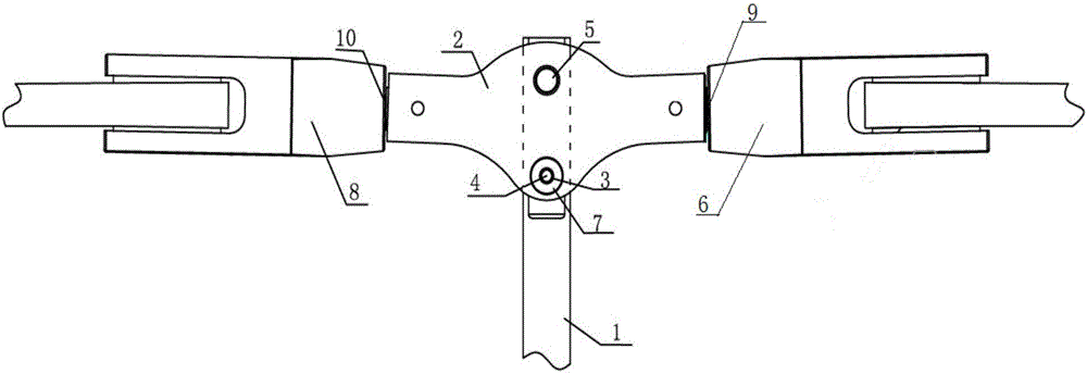
[0023] Such as figure 1 , the present invention provides a UAV main rotor, the UAV main rotor includes: a rotating main shaft 1, a blade connector 2, a first blade 8, a second blade 6 and a fixing member, the rotating The main shaft 1 is vertically arranged on the body of the drone, and the paddle connector 2 is arranged horizon...


PUM


Abstract

The invention discloses a main rotor of an unmanned aerial vehicle. The main rotor of the unmanned aerial vehicle comprises a rotating spindle, a paddle connecting part, a first paddle, a second paddle and a fixing part. The rotating spindle is vertically arranged on a body of the unmanned aerial vehicle, the paddle connecting part is horizontally arranged and fixed on the rotating spindle through a first fixing pin, a fixing hole matched with the fixing part is formed in the rotating spindle, the first paddle and the second paddle are arranged at the two ends of the paddle connecting part, the fixing part comprises a stop cover, a second fixing pin and a cylindrical buffer part, the buffer part is connected to the peripheral face of the second fixing pin, the stop cover is arranged at one end of the second fixing pin, the other end of the second fixing pin extends out of the buffer part and is fixed to the rotating spindle, the area of the stop cover is greater than that of the fixing hole, the fixing part is arranged in the fixing hole, and the buffer part is abutted to the inner wall of the fixing hole. By applying the main rotor of the unmanned aerial vehicle, the defects that in the prior art, the unmanned aerial vehicle is instable in flight, parts of the unmanned aerial vehicle are worn quickly, and the unmanned aerial vehicle is difficult to meet the requirement for precise control over flight are overcome.

Description

technical field [0001] The invention relates to the field of the main rotor of an unmanned aerial vehicle. Background technique [0002] At present, the main rotor of UAVs commonly used is usually to install the blade connecting shaft on the rotating main shaft through a fixed pin, and then install the blades at both ends of the blade connecting shaft respectively. During the forward flight of the UAV, due to the The periodic change of the blade air flow field causes the unbalanced aerodynamic force on it, and the connecting shaft of the blade rotates around the main axis of rotation and oscillates at the same time, thus performing a seesaw movement. It will lead to unstable flight of the UAV, and the parts on the UAV will wear out faster, and it is prone to breakage between the rotating shaft and the connecting shaft of the blade. It is difficult for the UAV to meet the requirements of precise flight control. Contents of the invention [0003] Aiming at the above-mention...

Claims


Application Information

Patent Timeline
IPC IPC(8): B64C11/12
CPCB64C11/008B64C11/12
Inventor 谢晓虎国贞君李孝阔孙存学
Owner WUHU WANHU AEROSPACE SCI & TECH CO LTD
Why Eureka
Try Eureka