A transmission device for supporting rollers

A transmission device and supporting roller technology, which is applied in the direction of transportation and packaging, conveyors, rotary conveyors, etc., can solve the problems of large space occupation and complex structure, and achieve saving of use area, simple structure and small space occupation Effect

Active Publication Date: 2018-03-20
KUSN KENSETABU BUHIN
View PDF6 Cites 0 Cited by
  • Summary
  • Abstract
  • Description
  • Claims
  • Application Information

AI Technical Summary

Problems solved by technology

The transmission of the existing rollers is usually realized by the transmission belt, the structure is relatively complicated, and it takes up a lot of space

Method used


Image

  • A transmission device for supporting rollers
  • A transmission device for supporting rollers
  • A transmission device for supporting rollers

Examples


Embodiment

[0019] Examples: The following specific examples illustrate the implementation of the present invention, and those skilled in the art can easily understand other advantages and effects of the present invention from the content disclosed in this specification. The descriptions of "above", "below", "top" and "bottom" mentioned in this embodiment are defined according to the usual meaning, for example, with reference to the definition of the direction of gravity, the direction of gravity is below, and opposite The direction is above, and similarly above is the top or the top, and below is the bottom or the bottom, which is only for the convenience of description, and is not used to limit the scope of the present invention. The change or adjustment of its relative relationship, Without substantive changes in technical content, it should also be regarded as the scope of implementation of the present invention.

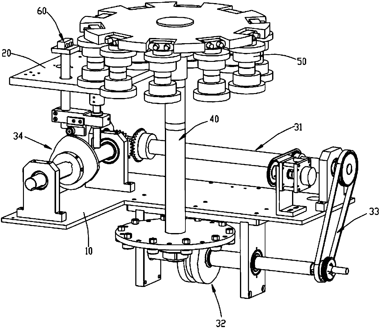
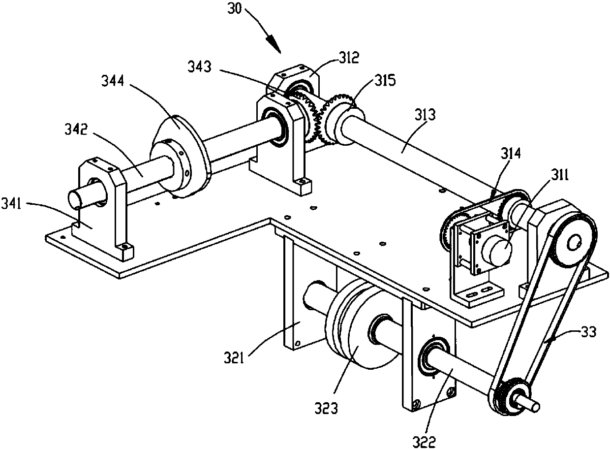
[0020] See figure 1 and figure 2 As shown, a transmission device fo...


PUM


Abstract

The invention discloses a transmission device of a bearing wheel. The transmission device comprises a first base plate, a transmission shaft unit and a rotating disc unit, wherein the transmission shaft unit is installed on the first base plate, and comprises a first transmission shaft unit body located above the first base plate, a second transmission shaft unit body located below the first base plate and a second belt transmission unit for connecting the first transmission shaft unit body and the second transmission shaft unit body; the second transmission shaft unit body comprises a second shaft base, a second rotating shaft and a driving wheel, the driving wheel is a cylinder, and a groove is formed in the circumference wall face of the driving wheel, and comprises a main groove part extending in the circumferential direction of the driving wheel and a leading-in part and a leading-out part, wherein the leading-in part and the leading-out part are formed in the two ends of the main groove part; the rotating disc unit is matched with the second transmission shaft unit body. The transmission device has the advantages of being simple in structure and small in occupied space.

Description

Technical field: [0001] The invention relates to the technical field of transmission devices, and more specifically relates to a transmission device for rollers. Background technique: [0002] In the current industrial and agricultural production, operations such as excavation and transfer of earthwork are often involved. In such operations, large-scale excavation equipment and bulldozing equipment are often used. Among these equipment, crawler machinery is usually used, such as Tracked excavators, tracked bulldozers and crawler tractors, etc., the track rollers are mainly used to carry the weight of bulldozers and excavators, so that the tracks can move forward along the rolling direction of the track rollers. Therefore, the track rollers are track An important part of mechanical equipment. In the production process of the roller, it is necessary to use a transmission device that makes the roller produce a certain displacement, so as to facilitate the processing of the rol...

Claims


Application Information

Patent Timeline
Patent Type & Authority Patents(China)
IPC IPC(8): B65G29/00
CPCB65G29/00B65G2201/0214
Inventor 周雪龙燕伟冯强
Owner KUSN KENSETABU BUHIN
Why Eureka
Try Eureka