Butterfly device for grading system

A grading system and butterfly valve technology, applied in the direction of valve device, valve operation/release device, valve lift, etc., can solve the problems of damaging the printed product printing system, difficulty in effectively closing the butterfly valve, and increasing the difficulty of closing, so as to maintain barrier, The effect of precise feeding

Pending Publication Date: 2020-12-11
JIANGSU VILORY ADVANCED MATERIALS TECH CO LTD
View PDF0 Cites 0 Cited by
  • Summary
  • Abstract
  • Description
  • Claims
  • Application Information

AI Technical Summary

Problems solved by technology

[0002] Butterfly valves need to be installed in the material conveying classification system to realize material flow control, especially in 3D printing systems, butterfly valves need to be used to achieve more accurate material conveying; although the existing butterfly valves have the characteristics of simple structure and low cost, but Because this type of butterfly valve only uses the valve stem to twist the valve plate to realize the conduction and closure of the butterfly valve, it increases the difficulty of closing invisibly. When an emergency occurs and the material to be transmitted has a high viscosity, it is necessary to stop the entire material transmission When it is difficult to effectively close the butterfly valve, it will bring the risk of damaging the printed product or the entire printing system. Therefore, it is an important reality to develop a butterfly valve device with a classification system that can achieve continuous or intermittent accurate feeding and effectively close. meaningful

Method used


Image

  • Butterfly device for grading system
  • Butterfly device for grading system

Examples


Embodiment 1

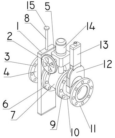
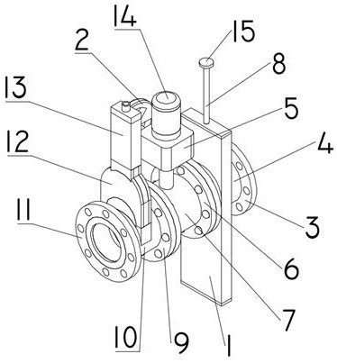
[0023] Such as Figure 1~2 As shown, a classification system butterfly valve device includes a first throttling structure, a second throttling structure and an emergency stop structure. The first throttling structure includes a first conduit 4, a first stop chamber 1, a first valve plate, The first valve stem 8 and the spring, the middle part of the first conduit 4 is connected with the first stop chamber 1 by welding, the middle part of the first conduit 4 communicates with the first stop chamber 1, and the middle part of the first valve plate is provided with The through hole, the first valve plate and the spring are all arranged inside the first stop chamber 1, and the two ends of the spring are respectively connected with the first valve plate and the inner wall of the first stop chamber 1 by welding, and the first valve stem One end of 8 is connected with the first valve plate by welding, and the other end of the first valve rod 8 is arranged outside the first stop chambe...


PUM

PropertyMeasurementUnit
Stiffnessaaaaaaaaaa

Abstract

The invention discloses a butterfly device for a grading system. The butterfly device comprises a first throttling structure, a second throttling structure and a scramming structure. The first throttling structure comprises a first guide pipe, a first intercepting cabin, a first valve plate, a first valve rod and a spring. The first valve plate is provided with a through hole. The first valve plate and the spring are arranged in the first intercepting cabin. Two ends of the spring are connected to the inner walls of the first valve plate and the first intercepting cabin, separately. One end ofthe first valve rod is connected to the first valve plate. The second throttling structure comprises a second guide pipe, a second valve plate, a second valve rod, a motor and a coupling. The secondvalve plate is connected to the inner wall of the second guide pipe through the second valve rod. The motor is connected to the second valve rod through the coupling. The scramming structure comprisesa third guide pipe, a second intercepting cabin, a third valve plate and an air cylinder. The air cylinder is provided with a transmission bar. The transmission bar is connected to the third valve plate. The butterfly device has the advantages of being accurate to feed, safe and reliable and the like, so that the butterfly device can be widely applied to the field of pipeline engineering.

Description

technical field [0001] The invention relates to the field of pipeline engineering, in particular to a classification system butterfly valve device. Background technique [0002] Butterfly valves need to be installed in the material conveying classification system to realize material flow control, especially in 3D printing systems, it is necessary to use butterfly valves to achieve more accurate material conveying; although the existing butterfly valves have the characteristics of simple structure and low cost, but Because this type of butterfly valve only uses the valve stem to twist the valve plate to realize the conduction and closure of the butterfly valve, it increases the difficulty of closing invisibly. When an emergency occurs and the material to be transmitted has a high viscosity, it is necessary to stop the entire material transmission When it is difficult to effectively close the butterfly valve, it will bring the risk of damaging the printed product or the entire...

Claims


Application Information

Patent Timeline
IPC IPC(8): F16K13/00F16K1/18F16K1/32F16K3/02F16K3/30F16K3/314F16K27/02F16K27/04F16K31/05F16K31/12
CPCF16K1/18F16K1/32F16K3/02F16K3/30F16K3/314F16K13/00F16K27/0209F16K27/044F16K31/055F16K31/12
Inventor 许荣玉唐跃跃蒋保林叶国晨张柯魏放蒋陈俞洋
Owner JIANGSU VILORY ADVANCED MATERIALS TECH CO LTD
Why Eureka
Try Eureka