
Rail train

a rail train and rail technology, applied in the field of rail trains, can solve the problems of increased side loads on the stands, uneven rail design, and stress on the trucks and couplers, and achieve the effect of minimizing side loads

Active Publication Date: 2012-05-22
HERZOG CONTRACTING
View PDF35 Cites 19 Cited by
  • Summary
  • Abstract
  • Description
  • Claims
  • Application Information

AI Technical Summary

Benefits of technology

This design minimizes side loads on the rail train by allowing uniform rail flexing and enhances worker safety by enabling remote operation of clamping and rail manipulation, simplifying the unloading process.

Problems solved by technology

A basic problem with existing rail trains is that the design of the cars does not allow the rails to flex evenly as the train traverses a curve.
This uneven flexion of the rails causes increased side loads on the stands, as well as stress on the trucks and couplers.
Worker safety is further endangered by the need to manually clamp and unclamp the rails using an impact wrench or the like.
A further problem with prior art rail trains is the limited usefulness of the end car ramp for maneuvering rail.
The ramp can support the rail during unloading and can raise and lower the rail within a limited range, but it cannot maneuver the rail inwardly or outwardly.
Furthermore, the ramp cannot support a rail in an upright position during unloading and there is a danger of the rail tipping over.

Method used


Image

  • Rail train
  • Rail train
  • Rail train

Examples


Embodiment Construction

[0049]As required, detailed embodiments of the present invention are disclosed herein; however, it is to be understood that the disclosed embodiments are merely exemplary of the invention, which may be embodied in various forms. Therefore, specific structural and functional details disclosed herein are not to be interpreted as limiting, but merely as a basis for the claims and as a representative basis for teaching one skilled in the art to variously employ the present invention in virtually any appropriately detailed structure. The drawings constitute a part of this specification and include exemplary embodiments of the present invention and illustrate various objects and features thereof.

[0050]Certain terminology will be used in the following description for convenience in reference only and will not be limiting. For example, the words “upwardly,”“downwardly,”“rightwardly,” and “leftwardly” will refer to directions in the drawings to which reference is made. The words “inwardly” a...


PUM


Abstract

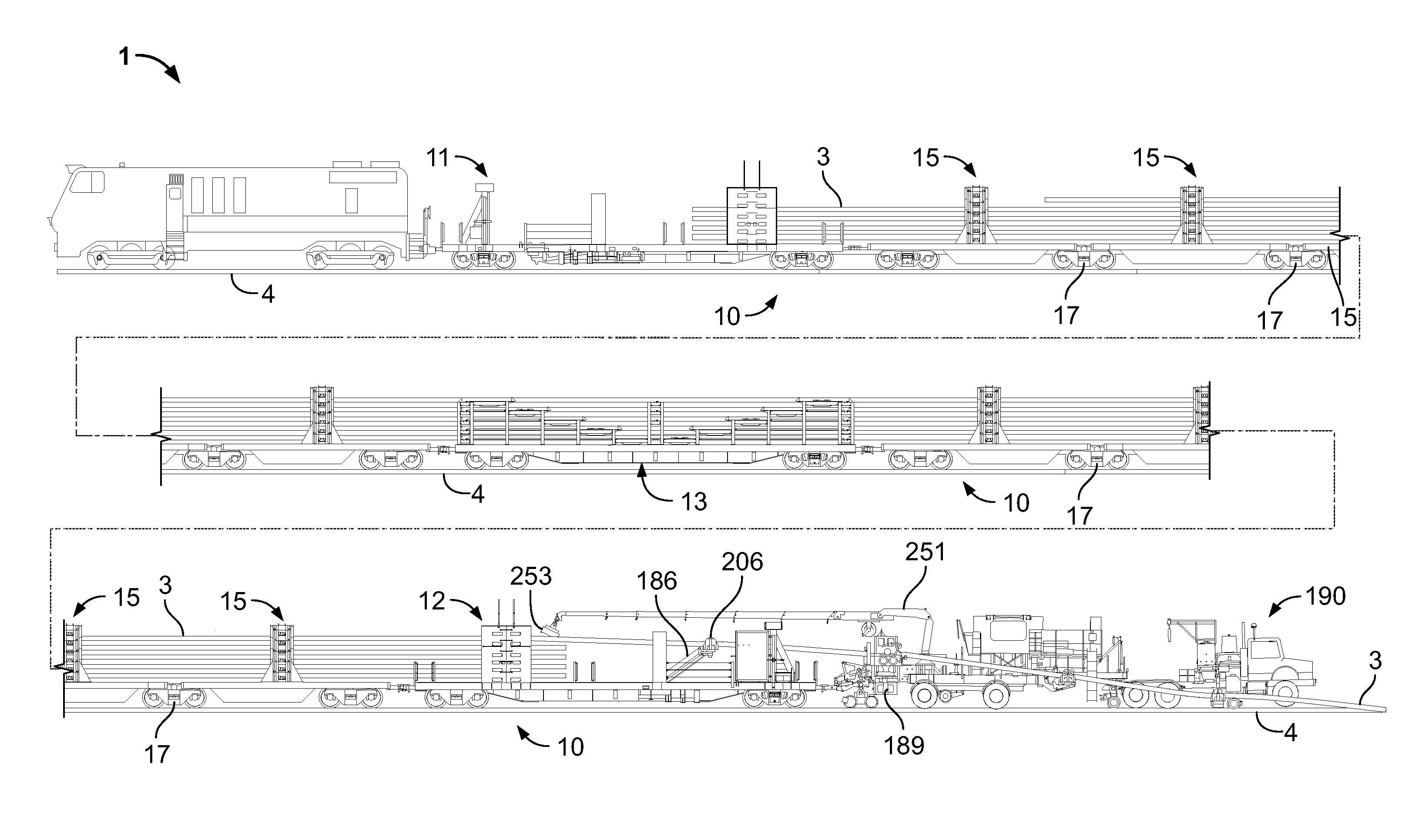
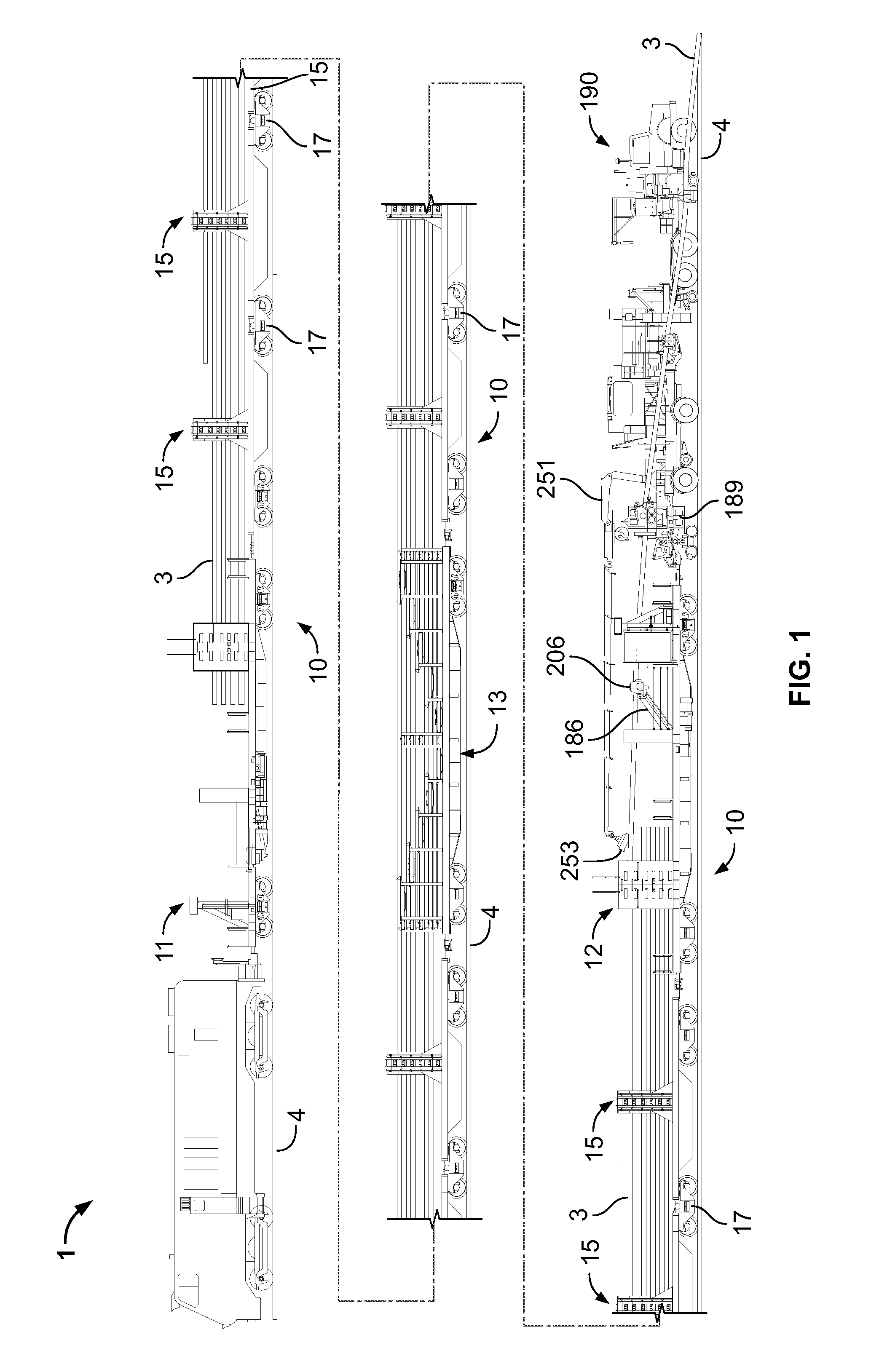
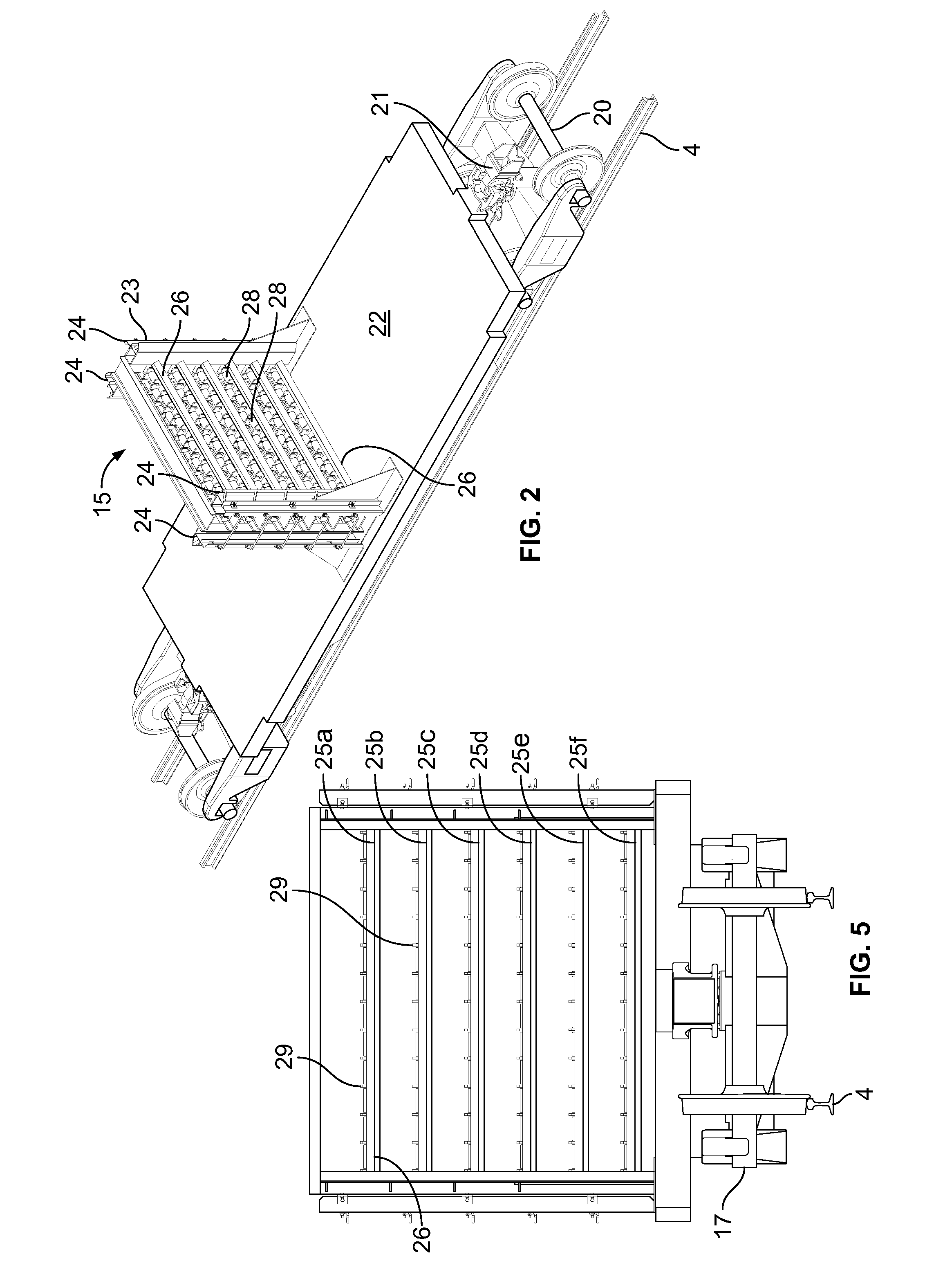
A rail train for supporting multiple sticks of ribbon rail comprises a plurality of rail support cars having a single, centrally positioned rail support stand wherein adjacent rail support cars are supported on shared trucks. End cars include a tunnel for supporting the rails near their ends and one or more rail support arms pivotal at a first end about two axis and supporting a rail guide assembly at a second end for supporting a rail as it is pulled of the rail train. A rail tie-down car utilizes spring-loaded, hydraulically actuated clamp assemblies to clamp individual rails to the tie-down car. Each clamp assembly incorporates at least two clamp members which act opposite one another to prevent the rail secured in place by the clamps from sliding in either longitudinal direction.

Description

BACKGROUND OF THE INVENTION[0001]1. Field of the Invention[0002]This invention relates to trains for carrying railroad rails, and in particular trains for carrying long lengths of ribbon rail.[0003]2. Description of the Related Art[0004]Modern railroad tracks are constructed using long sections of ribbon rail which presently may be up to 1600 feet in length. These sections of ribbon rail are formed by butt welding multiple sticks of rail, which traditionally come from the steel mill in thirty-nine foot or seventy-eight foot lengths. The welding of the ribbon rails is done at a welding plant and the welded ribbon rails are transported to their installation site on a specially constructed rail train. When existing track is being replaced, ribbon rails may be unloaded from the rail train using a rail unloading machine, such as the Rail unloading machines disclosed in U.S. Pat. No. 6,981,452 and U.S. Patent Application Publication No. 2008 / 0141893, both to Herzog et al. The rail unloadi...

Claims


Application Information

Patent Timeline
Patent Type & Authority Patents(United States)
IPC IPC(8): E01B29/16
CPCE01B29/17Y10T24/44299
Inventor BOUNDS, IVAN E.
Owner HERZOG CONTRACTING
Learn More