
Double-station power battery cover plate laser welding machine and welding method

A laser welding machine and power battery technology, applied in laser welding equipment, welding equipment, manufacturing tools, etc., can solve problems such as difficulty in improving welding production capacity, poor safety, and difficult movement of welding head, so as to ensure yield and accuracy , high safety and convenient feeding

Pending Publication Date: 2018-03-13
DONGGUAN GLORYSTAR LASER TECH
View PDF6 Cites 19 Cited by
  • Summary
  • Abstract
  • Description
  • Claims
  • Application Information

AI Technical Summary

Problems solved by technology

[0003] First, the existing power battery cover laser welding machine is a single-station laser welding machine. After the laser welding head has welded the previous set of power battery cover plates, it must wait for the latter set of power battery cover plates to reach the welding position. The latter group of power battery covers can be welded, and the laser welding head is expensive, which causes the problem of low utilization of the laser welding head, and it is difficult to increase the welding capacity; when two or more power battery covers need to be welded Laser welding cannot be performed at the same time, and only one type of power battery cover can be welded before welding another type of power battery cover;
[0004] Second, the existing power battery cover laser welding machine has no screw feeding device, which has poor safety, and the power battery cover is fixed by clamps, and the fixed product is unstable;
[0005] Third, the welding head of the laser welding system of the existing power battery cover laser welding machine is difficult to move in the three directions of X, Y, and Z, and it is difficult to adjust the distance between the laser welding system and the power battery cover
[0006] Fourth, the existing power battery cover laser welding machine is not equipped with a CCD positioning device, and the welding accuracy cannot be guaranteed

Method used


Image

  • Double-station power battery cover plate laser welding machine and welding method
  • Double-station power battery cover plate laser welding machine and welding method
  • Double-station power battery cover plate laser welding machine and welding method

Examples


Embodiment Construction

[0044] The structural principle and working principle of the present invention will be further described in detail below in conjunction with the accompanying drawings.

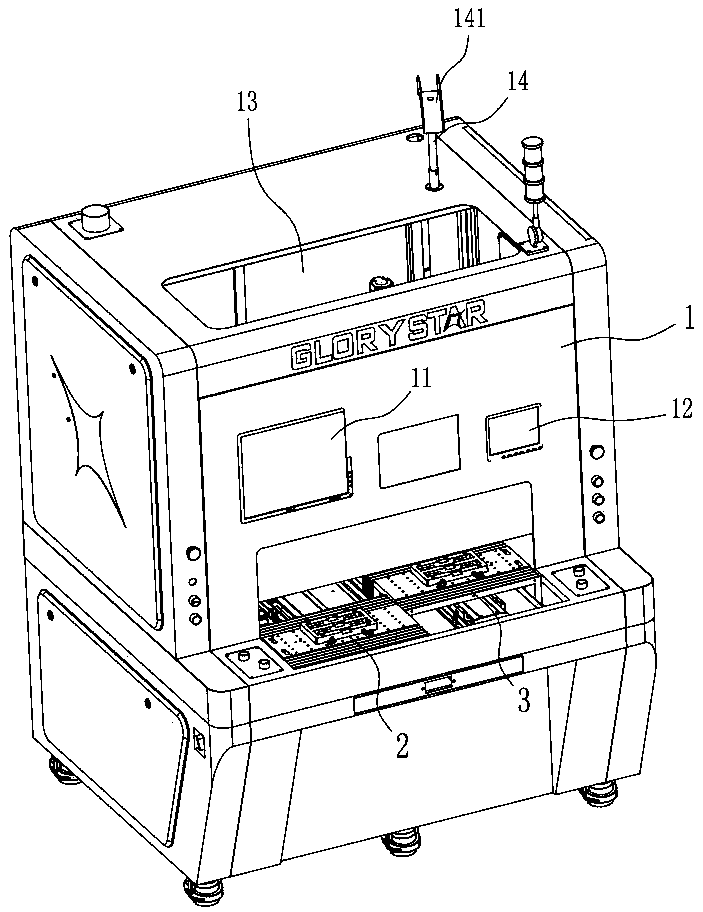
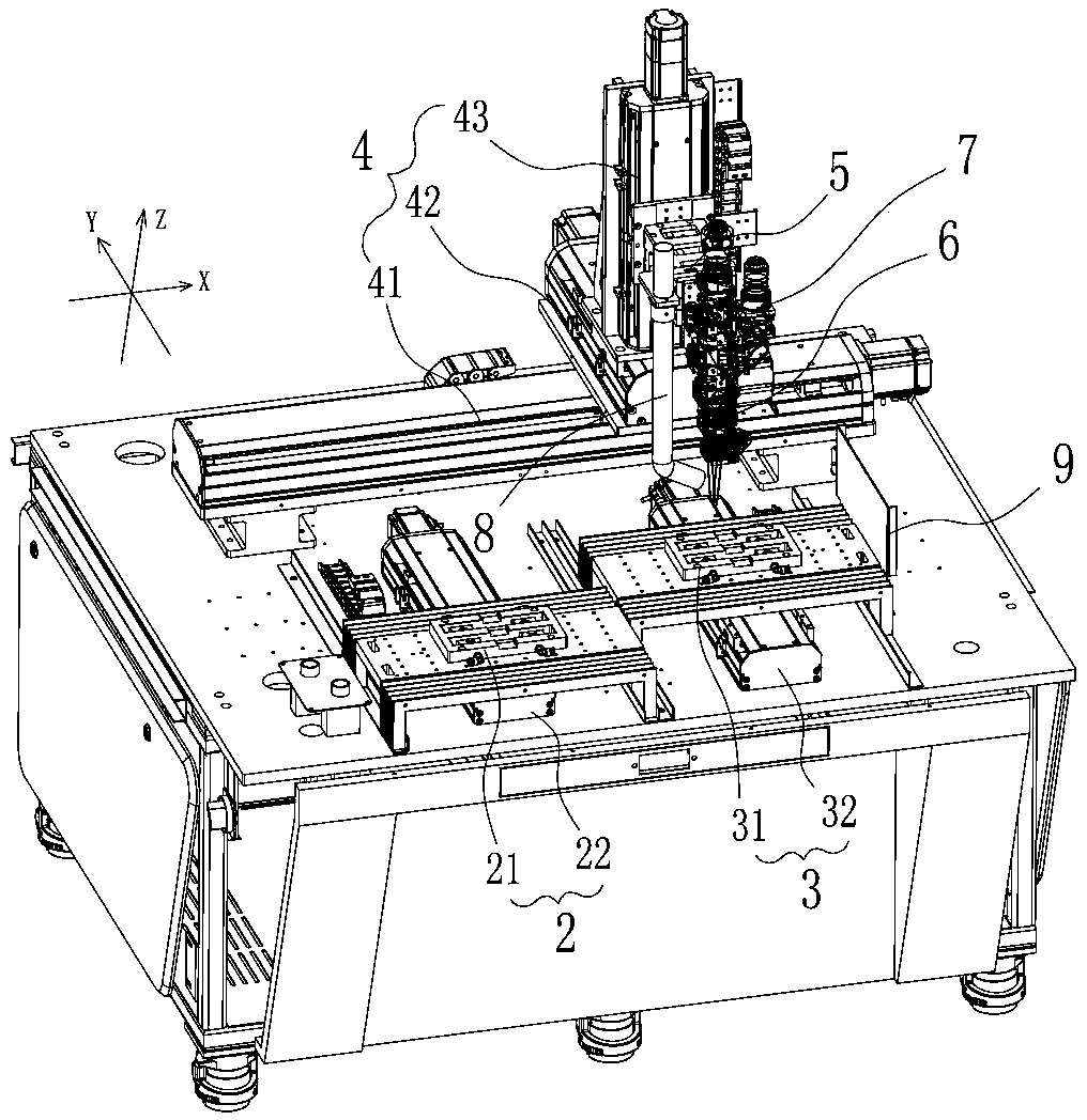
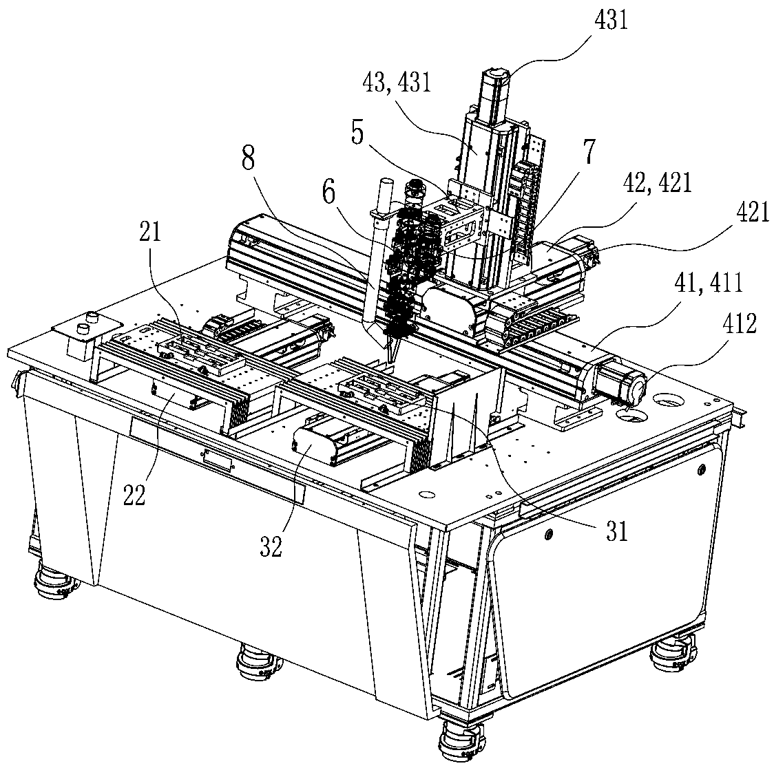
[0045] Such as Figure 1-Figure 5 As shown, the present invention is a double-station power battery cover laser welding machine, which is used for welding pole pieces on the power battery cover. The present invention includes a control system, a first power battery cover feeding system 2 electrically connected to the control system, a second power battery cover feeding system 3, an XYZ axis transmission system 4, a welding head 5, a laser welding system 6 and a CCD The positioning system 7, the first power battery cover feeding system 2 and the second power battery cover feeding system 3 are installed side by side along the X-axis direction, wherein:

[0046] The first power battery cover feeding system 2 includes a first Y-axis power battery cover transmission device 21 and a first vacuum adsorption position...


PUM


Abstract

The invention discloses a double-station power battery cover plate laser welding machine and a welding method. The power battery cover plate laser welding machine comprises a control system, and a first power battery cover plate feeding system, a second power battery cover plate feeding system, an XYZ-axle transmission system, a welding machine head, a laser welding system and a CCD positioning system electrically connected with the control system; and the first power battery cover plate feeding system and the second power battery cover plate feeding system are mounted in the X-axle directionside by side. The power battery cover plate laser welding machine is convenient to feed and high in welding efficiency, realizes movement in X, Y and Z directions, can adjust distances from the laserwelding device to products, can fix the products through vacuum absorption, can determine positioning errors through CCD positioning, and can compensate error values from the X, Y and Z directions.

Description

technical field [0001] The invention relates to the technical field of laser welding equipment, in particular to a laser welding machine and a welding method for a double-station power battery cover plate. Background technique [0002] At present, the power battery cover plate and the pole piece of the power battery are mainly welded by a laser welding machine. In the prior art, the power battery cover laser welding machine has the following defects: [0003] First, the existing power battery cover laser welding machine is a single-station laser welding machine. After the laser welding head has welded the previous set of power battery cover plates, it must wait for the latter set of power battery cover plates to reach the welding position. The latter group of power battery covers can be welded, and the laser welding head is expensive, which causes the problem of low utilization of the laser welding head, and it is difficult to increase the welding capacity; when two or more...

Claims


Application Information

Patent Timeline
Patent Type & Authority Applications(China)
IPC IPC(8): B23K26/08B23K26/21B23K26/70
CPCB23K26/0884B23K26/21B23K26/702
Inventor 姚玉东尹德生周凌王海亮肖列民赵浩然
Owner DONGGUAN GLORYSTAR LASER TECH
Learn More