Shock isolation device

A technology of vibration isolation and vibration isolation body, which is applied in the direction of shock absorber, spring/shock absorber, shock absorber, etc., and can solve the problems that the isolated object is easy to break away from the vibration isolation device, and the vibration isolation support cannot be self-locked. , to achieve the effect of good self-locking function

Inactive Publication Date: 2016-11-09
CHINA ELECTRIC POWER RES INST +1
View PDF5 Cites 2 Cited by
  • Summary
  • Abstract
  • Description
  • Claims
  • Application Information

AI Technical Summary

Problems solved by technology

[0004] In view of this, the present invention proposes a shock-isolating device, which aims to solve the problem that the existing shock-isolating support cannot be self-locked, causing the object to be isolated to be easily detached from the shock-isolating device

Method used


Image

  • Shock isolation device
  • Shock isolation device
  • Shock isolation device

Examples


Embodiment Construction

[0021] Exemplary embodiments of the present disclosure will be described in more detail below with reference to the accompanying drawings. Although exemplary embodiments of the present disclosure are shown in the drawings, it should be understood that the present disclosure may be embodied in various forms and should not be limited by the embodiments set forth herein. Rather, these embodiments are provided for more thorough understanding of the present disclosure and to fully convey the scope of the present disclosure to those skilled in the art. It should be noted that, in the case of no conflict, the embodiments of the present invention and the features in the embodiments can be combined with each other. The present invention will be described in detail below with reference to the accompanying drawings and examples.

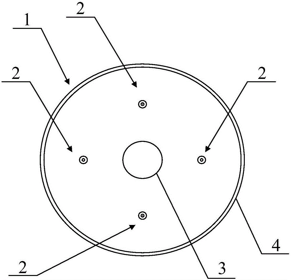
[0022] see figure 1 , figure 1 It is a top view of the vibration isolation device provided by the embodiment of the present invention. As shown in the figu...


PUM


Abstract

The invention provides a shock isolation device, which comprises a shock isolation body and a position limiting mechanism, wherein the shock isolation body is provided with a first through hole in the axial direction; the position limiting mechanism is arranged in the first through hole, and is connected with the shock isolation body. The shock isolation device provided by the invention comprises the shock isolation body and the position limiting mechanism; the position limiting mechanism is arranged in the through hole formed in the shock isolation body; the position limiting mechanism is connected with the shock isolation body; when the shock isolation body generates transverse deformation due to shock, the hole diameter of the first through hole can be reduced in the deformation direction; therefore the shock isolation body can extrude the position limiting mechanism; the position limiting mechanism can limit the shock isolation body to generate too great transverse deformation after being extruded by the shock isolation body, so that the shock isolation device has a good self locking function; further, an object which is subjected to shock isolation and is connected with the upper part of the shock isolation device can be effectively prevented from generating too great horizontal displacement to be disengaged from the shock isolation device.

Description

technical field [0001] The present invention relates to the technical field of power systems, in particular to a shock isolation device. Background technique [0002] The box-type electrical main equipment in buildings and substations is relatively heavy, but when a large earthquake occurs, the damage to the building will cause great casualties, and the main electrical equipment may leave its original position and shift or drop phenomenon. In addition, the bushing on the equipment body is a weak link that is prone to damage. Under the action of a large earthquake, the root of the porcelain bushing will often break or shift, and then it is necessary to isolate the building and electrical equipment. [0003] At present, the seismic isolation of buildings and electrical equipment usually uses seismic isolation bearings, but the existing seismic isolation bearings cannot be self-locked when an earthquake occurs, and excessive lateral deformation is prone to occur in the event o...

Claims


Application Information

Patent Timeline
Patent Type & Authority Applications(China)
IPC IPC(8): F16F7/104
CPCF16F7/104
Inventor 程永锋卢智成高坡刘洪涛王晓宁俞越中孙宇晗刘振林孟宪政
Owner CHINA ELECTRIC POWER RES INST
Why Eureka
Try Eureka