
Air outlet mechanism and air conditioner indoor unit

A drive mechanism, centrifugal fan technology, applied in heating and ventilation hoods/covers, space heating and ventilation details, domestic heating, etc., can solve problems such as inability to adjust the direction of the wind

Inactive Publication Date: 2016-11-09
GREE ELECTRIC APPLIANCES INC
View PDF5 Cites 7 Cited by
  • Summary
  • Abstract
  • Description
  • Claims
  • Application Information

AI Technical Summary

Problems solved by technology

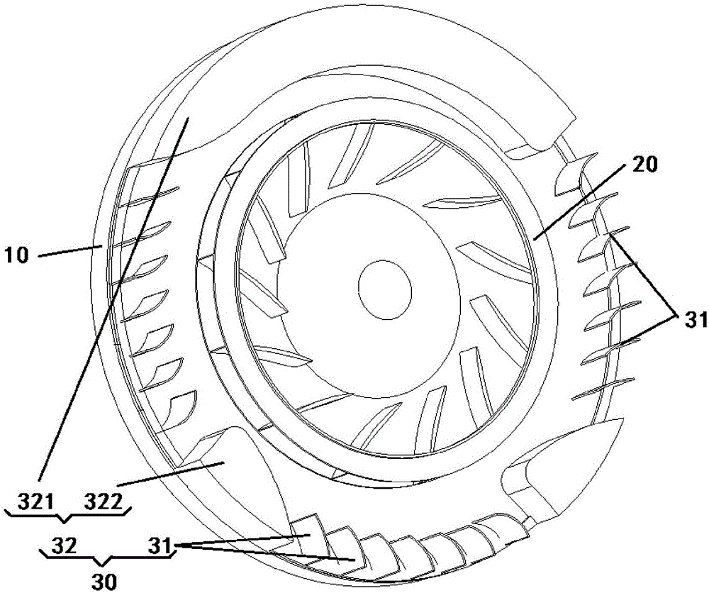
[0004] The main purpose of the present invention is to provide an air outlet mechanism and an air conditioner indoor unit to solve the problem in the prior art that the circular air outlet of the wall-mounted unit cannot adjust the air outlet direction

Method used


Image

  • Air outlet mechanism and air conditioner indoor unit
  • Air outlet mechanism and air conditioner indoor unit
  • Air outlet mechanism and air conditioner indoor unit

Examples


Embodiment Construction

[0031] It should be noted that, in the case of no conflict, the embodiments of the present invention and the features in the embodiments can be combined with each other. The present invention will be described in detail below with reference to the accompanying drawings and examples.

[0032] In order to enable those skilled in the art to better understand the solutions of the present invention, the following will clearly and completely describe the technical solutions in the embodiments of the present invention in conjunction with the drawings in the embodiments of the present invention. Obviously, the described embodiments are only It is an embodiment of a part of the present invention, but not all embodiments. Based on the embodiments of the present invention, all other embodiments obtained by persons of ordinary skill in the art without making creative efforts shall fall within the protection scope of the present invention.

[0033] It should be noted that the terms "first...


PUM


Abstract

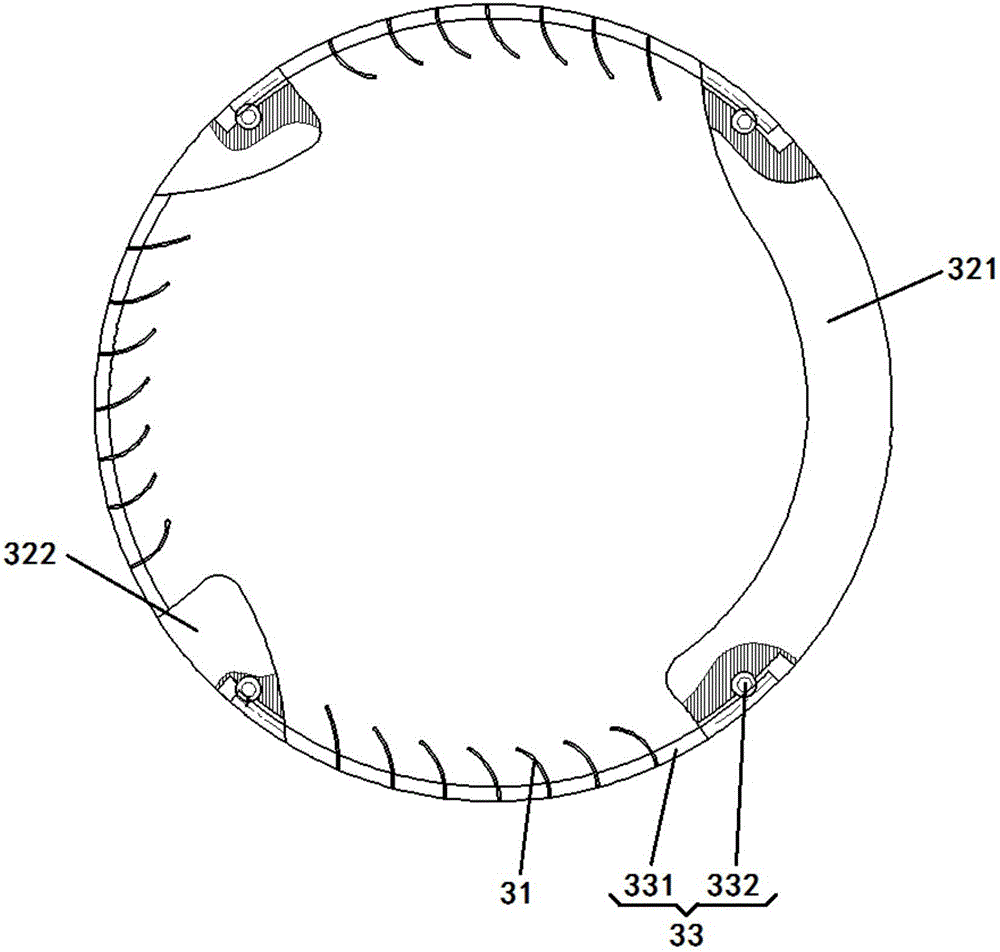
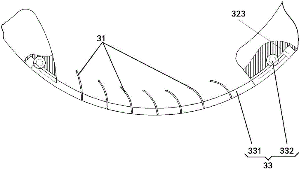
The invention provides an air outlet mechanism and an air conditioner indoor unit. The air outlet mechanism comprises a bottom case, a centrifugal fan and an air guide component, wherein the centrifugal fan is arranged on the bottom case; the centrifugal fan sucks air flow towards the bottom case and blows out the air flow towards the peripheral direction of the centrifugal fan; the air guide component is movably arranged on the bottom case and is positioned at the outer side of the centrifugal fan. When the air outlet mechanism works, the air flow is firstly sucked in towards the bottom case from a space opposite to the bottom case; then, the sucked air flow is blown out towards the peripheral direction of the centrifugal fan. The air guide component arranged in the peripheral direction of the centrifugal fan can guide the blown out air flow, so that the air flow can be blown out towards a preset position. Through the movable air guide component, the air outlet direction of the air outlet mechanism can be changed.

Description

technical field [0001] The invention relates to an air outlet mechanism and an air conditioner, in particular to an air outlet mechanism and an indoor unit of the air conditioner. Background technique [0002] At present, with the development of circular or nearly circular wall-mounted machines by various enterprises, the air duct forms of this type of air conditioner have also become various. [0003] However, due to the particularity of the circular or nearly circular wall-mounted air outlet, it is difficult to install a sweeping mechanism. Most of the products have a single air supply method, and the air can only be released along the direction guided by the air duct guide wall. Contents of the invention [0004] The main purpose of the present invention is to provide an air outlet mechanism and an indoor unit of an air conditioner, so as to solve the problem in the prior art that the circular air outlet of the wall-mounted unit cannot adjust the air outlet direction. ...

Claims


Application Information

Patent Timeline
IPC IPC(8): F24F13/15F24F13/20
CPCF24F13/15F24F13/20F24F2013/205
Inventor 赵万东彭勃刘汉李建建陈英强黎优霞夏增强廖敏
Owner GREE ELECTRIC APPLIANCES INC
Learn More