Solid dehumidifier

A dehumidifier, solid technology, applied in the separation of dispersed particles, chemical instruments and methods, separation methods, etc., can solve the problems affecting the dehumidification and regeneration efficiency, the weight of the runner, and the large size, etc., to improve the dehumidification and regeneration efficiency. Effect

Active Publication Date: 2016-01-20
GREE ELECTRIC APPLIANCES INC
View PDF5 Cites 2 Cited by
  • Summary
  • Abstract
  • Description
  • Claims
  • Application Information

AI Technical Summary

Problems solved by technology

[0005] 1. The volume is large and requires a high installation space;
[0006] 2. The weight of the runner is heavy, and the required drive motor power is high, which directly affects the efficiency and energy efficiency of the whole machine;
[0007] 3. There is radiation heat in the dehumidification and regeneration process, which directly affects the dehumidification and regeneration efficiency

Method used


Image

  • Solid dehumidifier
  • Solid dehumidifier
  • Solid dehumidifier

Examples


Embodiment Construction

[0026] The present invention will be described in further detail below in conjunction with the accompanying drawings and specific embodiments, but not as a limitation of the present invention.

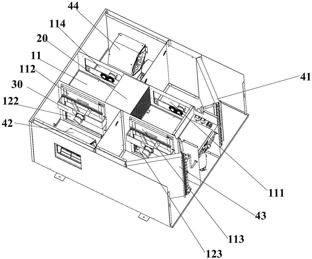
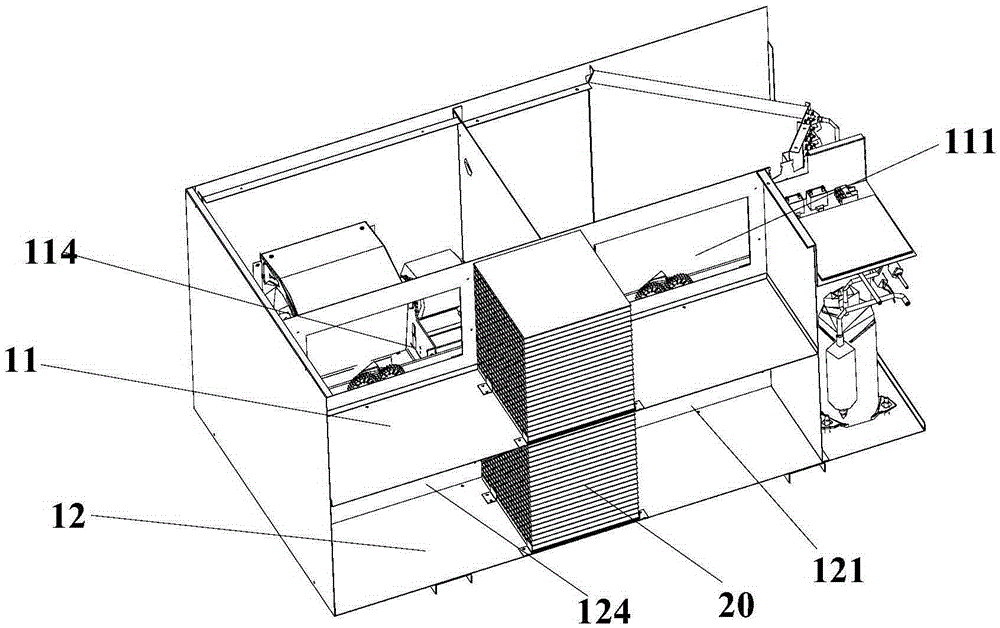
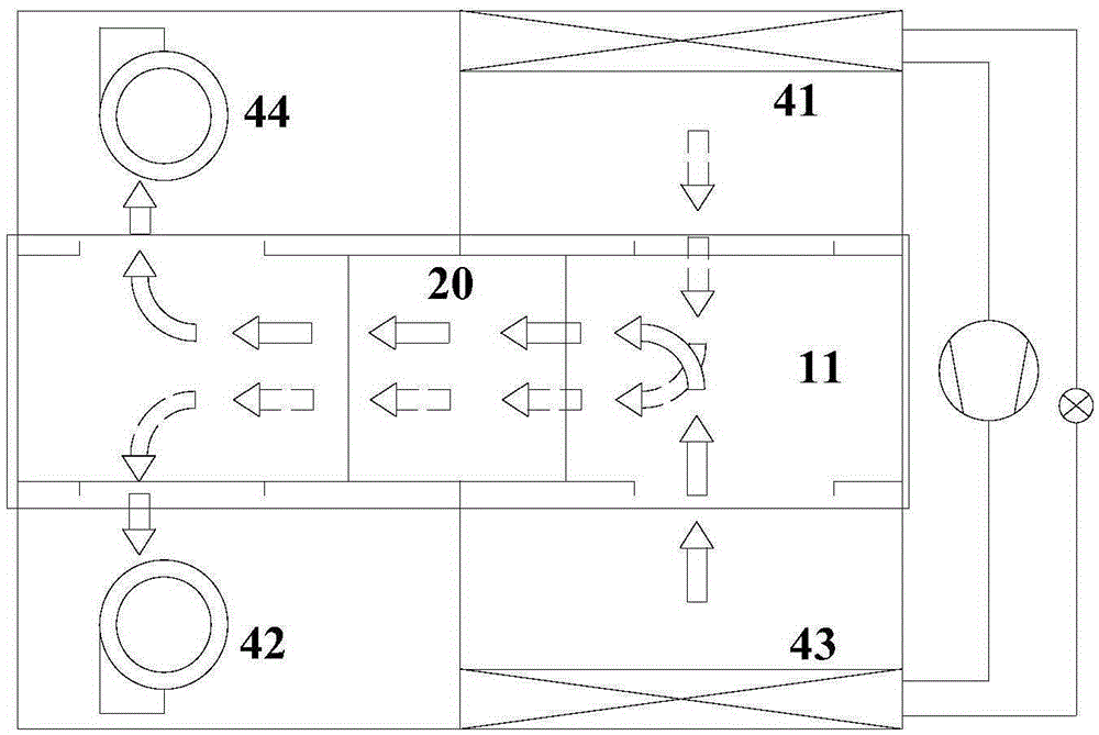
[0027] Such as Figure 1 to Figure 5 As shown, the embodiment of the present invention provides a solid dehumidifier, which includes: an upper air duct 11, a lower air duct 12, a fresh air assembly and a return air assembly. Both the upper air passage 11 and the lower air passage 12 are provided with solid dehumidification modules 20 . Both the upper air duct 11 and the lower air duct 12 are in communication with the fresh air assembly and the return air assembly. The wind direction switching device 30 is slidably arranged at the tuyere of the upper air passage 11 and the lower air passage 12, and the wind direction switching device 30 can selectively communicate the fresh air assembly with the upper air passage 11 and communicate the return air assembly with the lower air passage 12,...


PUM


Abstract

The invention discloses a solid dehumidifier which comprises an upper air flue, a lower air flue, a fresh air assembly, a return air assembly and a wind direction switch device. The upper air flue and the lower air flue are each internally provided with a solid dehumidifying module. The upper air flue and the lower air flue are connected with the return air assembly. The wind direction switch device is arranged on air openings of the upper air flue and the lower air flue. The wind direction switch device selectively enables the fresh air assembly to be communicated with the upper air flue or the lower air flue and enables the return air assembly to be communicated with the lower air flue or the upper air flue correspondingly. By the adoption of the technical scheme, air flue switch is achieved through the wind direction switch device, and the wind field flow direction is changed, so that fresh air and return air are switched in the two air flues, then fresh air is fed into the indoor space after being dehumidified through the solid dehumidifying module, the return air is exhausted to the outdoor space after carrying out regeneration on the dehumidified solid dehumidifying module, and the purpose of improving dehumidifying and regeneration efficiency is achieved.

Description

technical field [0001] The invention relates to the technical field of air conditioning, in particular to a solid dehumidifier. Background technique [0002] Most of the solid dehumidifiers currently on the market use the dehumidification method of the rotary wheel. The rotary dehumidifier is mainly composed of a rotary wheel, a regenerative heater and a regenerative fan. The rotary wheel is made of a glass fiber board filled with special metals. It is rolled into a honeycomb-shaped round wheel, and then impregnated with silicate moisture-absorbing agent by means of advanced technology. [0003] The solid dehumidifier in the prior art generally makes the runner rotate slowly at a speed of 30 revolutions per hour. After the humid air to be treated is filtered by the air filter, it enters the honeycomb channel of the 3 / 4 runner, so the moisture in the air Dry air passing through the rotor is sent into the room for silicate absorption. While the runner absorbs moisture, part ...

Claims


Application Information

Patent Timeline
Patent Type & Authority Applications(China)
IPC IPC(8): B01D53/26
Inventor 薛寒冬苏玉海余凯李卫国张红梅
Owner GREE ELECTRIC APPLIANCES INC
Why Eureka
Try Eureka