Air conditioner

An air conditioner, air conditioning technology, applied in air conditioning systems, space heating and ventilation details, control inputs involving air characteristics, etc., can solve problems such as user discomfort and inability to switch, achieve comfortable performance, prevent Unpleasant, efficiency-enhancing effects

Active Publication Date: 2009-12-02
SHARP KK
View PDF6 Cites 2 Cited by
  • Summary
  • Abstract
  • Description
  • Claims
  • Application Information

AI Technical Summary

Problems solved by technology

However, since the temperature around the indoor unit 1 becomes higher due to the concentrated heating, it cannot be switched to a "strong" wind speed, so the feet are cold, and the heating directly faces the head, which continues to bring discomfort to the user

Method used


Image

  • Air conditioner
  • Air conditioner
  • Air conditioner

Examples


no. 1 Embodiment approach

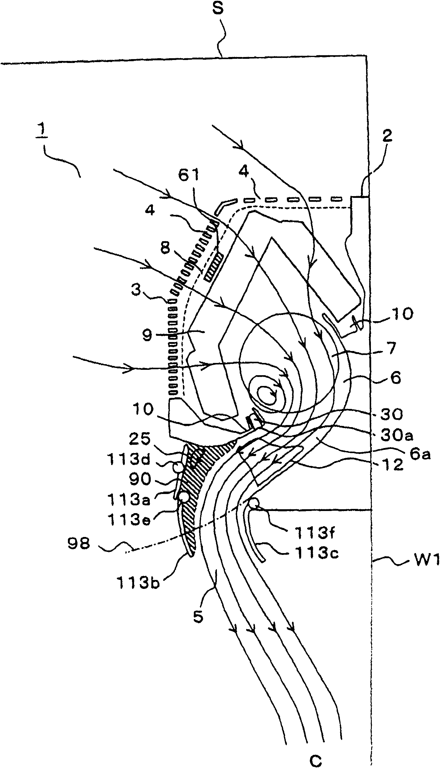
[0067] figure 1 It is a side sectional view showing the air conditioner of the first embodiment (showing Figure 8 D section). An indoor unit 1 of an air conditioner has a main body held by a casing 2, and a front panel 3 having a suction port 4 on the front side and a front side thereof is detachably attached to the casing 2.

[0068] The casing 2 is provided with a claw portion (not shown in the figure) on the rear side, and the claw portion cooperates with a mounting plate (not shown in the figure) installed on the side wall W 1 of the living room to support the casing 2 . An air outlet 5 is provided in a gap between the lower end of the front panel 3 and the lower end of the cabinet 2 . The air outlet 5 is formed in a substantially rectangular shape extending in the width direction of the indoor unit 1, and is provided facing forward and downward.

[0069] Inside the indoor unit 1 , a blower path 6 communicating from the suction port 4 to the blower port 5 is formed. ...

no. 2 Embodiment approach

[0129] then, Figure 16 It is a side cross-sectional view showing the air conditioner indoor unit 1 of the second embodiment. with the above Figure 1 to Figure 15 The parts that are the same as those of the first embodiment shown are denoted by the same symbols. In this embodiment, instead of the airflow direction variable sections 113a, 113b, and 113c of the first embodiment, airflow direction variable sections 114a and 114b are provided. Other parts are the same as those of the first embodiment.

[0130] The wind direction variable parts 114a, 114b are arranged at the blower outlet 5, and both surfaces are made of flat plates. The rotation shafts 114c, 114d rotatably support the wind direction variable parts 114a, 114b, and are rotationally driven by a drive motor (not shown). Therefore, the wind direction variable parts 114a and 114b are constituted by a wind direction plate whose direction is changed by driving of a drive motor. Moreover, the rotating shaft 114c is p...

no. 3 Embodiment approach

[0152] then, Figure 22 It is a side sectional view which shows the air conditioner indoor unit 1 which concerns on 3rd Embodiment. with the above Figure 16 ~ Figure 21 The same parts of the second embodiment shown are denoted by the same symbols. In this embodiment, instead of the wind direction variable parts 114a and 114b of the second embodiment, wind direction variable parts 115a and 115b are provided.

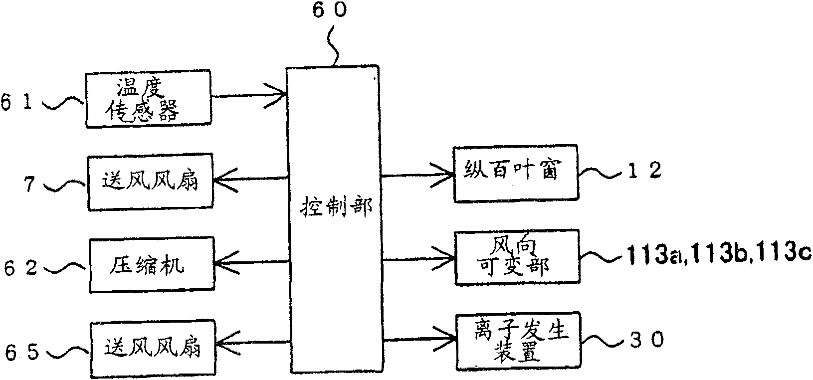
[0153] In addition, in order to detect the rotation speed of the blower fan 7 in the indoor unit 1, a rotation speed detection unit (not shown) for detecting the volume of conditioned air sent from the air outlet 5 is provided. in the above Figure 4 Among them, the output of the rotational speed detection unit is input to the control unit 60, and the wind direction variable units 115a and 115b are driven based on the detection result of the rotational speed detection unit. Other parts are the same as the second embodiment.

[0154] The wind direction variable parts...


PUM


Abstract

An indoor unit (1) of an air conditioner is installed on an upper part of a wall surface (W1), and a suction port (4) and a blowout port (5) are provided in a front part and a lower part, respectively, of the indoor unit (1). The blowout port (5) is fitted with wind deflectors (113a, 113b, and 113c) that can vary the blowout direction between a frontward-horizontal direction and a rearward-downward direction. At the start-up of heating, conditioned air is sent out obliquely downward toward the wall surface (W1). By the Coanda effect, the conditioned air goes down along the wall surface (W1), and then flows over a floor surface (F) to circulate inside the room. When the heating operation has stabilized, the wind deflectors (113a, 113b and 113c) are so driven to narrow the air stream path so that the conditioned air is sent out at a lower wind volume.

Description

technical field [0001] The present invention relates to an air conditioner which regulates the air sucked into a cabinet and sends the air out to the room. Background technique [0002] Conventional air conditioners are disclosed in Japanese Patent Application No. 2002-266437 and the like. Figure 28 Shows the path of airflow in a room when this type of air conditioning mechanism is running hot. The indoor unit 1 of the air conditioner is installed on the upper part of the side wall W1. The lower part of the indoor unit 1 is provided with an outlet (not shown) through which conditioned air is sent out. [0003] In the temperature rise state in which the room temperature rises rapidly after the start of the heating operation, it is necessary to circulate the indoor air rapidly. Therefore, as shown by the arrow B from the blower outlet (not shown in the figure), it is violently sent out substantially directly below at, for example, a "strong" wind speed (about 5 to 6 m / sec)....

Claims


Application Information

Patent Timeline
Patent Type & Authority Patents(China)
IPC IPC(8): F24F11/02F24F1/00F24F11/04
CPCF24F2221/54F24F2001/0048F24F1/0011F24F1/0057F24F2013/0616F24F11/62F24F11/79F24F2110/10F24F2110/20F24F2110/50F24F2140/60F24F8/30
Inventor 大塚雅生
Owner SHARP KK
Why Eureka
Try Eureka