Blower

A blower and wind direction technology, applied to mechanical equipment, machines/engines, liquid fuel engines, etc., can solve problems such as adjusting the direction of air supply and excessive power consumption

Active Publication Date: 2021-11-19
LG ELECTRONICS INC
View PDF3 Cites 2 Cited by
  • Summary
  • Abstract
  • Description
  • Claims
  • Application Information

AI Technical Summary

Problems solved by technology

[0004] On the other hand, in order to adjust the blowing direction of the conventional blower, it is necessary to install a plurality of motors driven independently or to move or rotate the blower.
Therefore, there are problems such as difficulty in adjusting the air blowing direction effectively and stepwise, or excessive power consumption.

Method used


Image

  • Blower
  • Blower
  • Blower

Examples


Embodiment Construction

[0063] By describing the embodiments in detail below with reference to the accompanying drawings, the advantages, features and implementation methods of the present invention will be more clearly understood. However, the present invention is not limited to the embodiments disclosed below, and can be embodied in various shapes that are different from each other. , the protection scope of the present invention is determined only by the scope of the claims. The same reference numerals denote the same constituent elements throughout the specification.

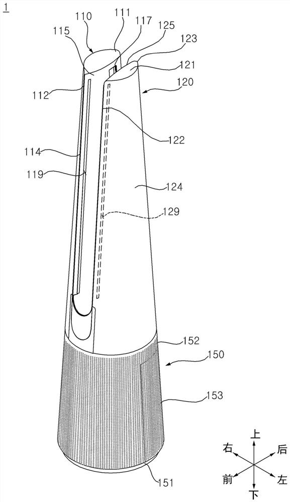
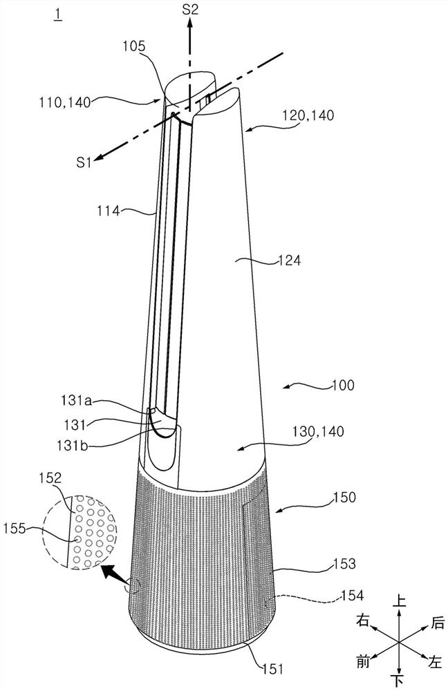
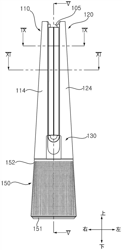
[0064] exist Figure 1 to Figure 11 , Figure 16 to Figure 17 , Figure 21 The direction marks of up, down, left, right, front and rear shown in are for convenience of description and do not limit the scope of the present invention. Therefore, if the reference changes, the direction can also be set differently.

[0065] refer to Figure 1 to Figure 4 , The air blower 1 includes a casing 100 providing an outer shape. The case...


PUM


Abstract

Provided is a blower comprising: a first tower in which a first discharge port is formed in a first wall; a second tower having a second wall facing the first wall and spaced apart from the first wall, the second wall having a second discharge port formed therein; a fan disposed on the lower side of the first tower and the second tower and forming an air flow to the first tower and the second tower, respectively; a first guide plate configured to be located inside the first tower or to protrude from the first wall; a second guide plate configured to be located inside the second tower or to protrude from the second wall; a first guide motor that changes a position of the first guide plate; and a second guide motor that changes a position of the second guide plate. A blowing gap is formed between the first wall and the second wall, air discharged from the first discharge port and the second discharge port flows in one direction in the blowing gap, and the first guide plate and the second guide plate are arranged in front of the blowing gap in a spaced manner from the first discharge port and the second discharge port respectively. Therefore, the direction of air flowing from the blowing gap is changed.

Description

technical field [0001] The present invention relates to blowers. In particular, the present invention relates to a blower capable of adjusting the blowing direction. Background technique [0002] The blower can circulate the air in the indoor space or create the air flow towards the user by creating the flow of air. In recent years, studies have been made on the air discharge structure of the blower that can provide comfort to the user. [0003] Regarding this, Korean authorized patents KR2011-0099318, KR2011-0100274, KR2019-0015325 and KR2019-0025443 disclose an air supply device and a fan for blowing air by using the Coanda effect. [0004] On the other hand, in order to adjust the blowing direction of the conventional air blower, it is necessary to provide a plurality of motors driven independently or to move or rotate the air blower. Therefore, there are problems such as difficulty in adjusting the blowing direction efficiently and stepwise, or excessive power consump...

Claims


Application Information

Patent Timeline
Patent Type & Authority Applications(China)
IPC IPC(8): F04F5/16F04F5/44
CPCF04F5/16F04F5/44F24F1/0014F24F8/10F04D25/10F04D25/14F04D29/524F04D29/563F04F5/466F04D25/0606F04D25/08F04D29/441F04D29/703
Inventor 郑载赫金起东金厚辰郑惠仁崔硕浩朴亨镐金容民崔致英
Owner LG ELECTRONICS INC
Why Eureka
Try Eureka