
Area projection optical 3D profilometry method for high dynamic range objects

A high dynamic range, three-dimensional profile technology, applied in the direction of optical devices, measuring devices, instruments, etc., can solve the problems of low measurement accuracy of high dynamic range objects, avoid overflow and saturation, solve low accuracy, and ensure measurement accuracy Effect

Active Publication Date: 2018-09-04
XI AN JIAOTONG UNIV
View PDF7 Cites 0 Cited by
  • Summary
  • Abstract
  • Description
  • Claims
  • Application Information

AI Technical Summary

Problems solved by technology

[0005] The purpose of the present invention is to overcome the above disadvantages and provide a method for area projection optical three-dimensional profile measurement of high dynamic range objects, which can solve the problem of low measurement accuracy of high dynamic range objects without increasing the complexity of the hardware system

Method used


Image

  • Area projection optical 3D profilometry method for high dynamic range objects
  • Area projection optical 3D profilometry method for high dynamic range objects
  • Area projection optical 3D profilometry method for high dynamic range objects

Examples


Embodiment Construction

[0028] The present invention will be further described below in conjunction with the accompanying drawings.

[0029] 1) Projection template acquisition

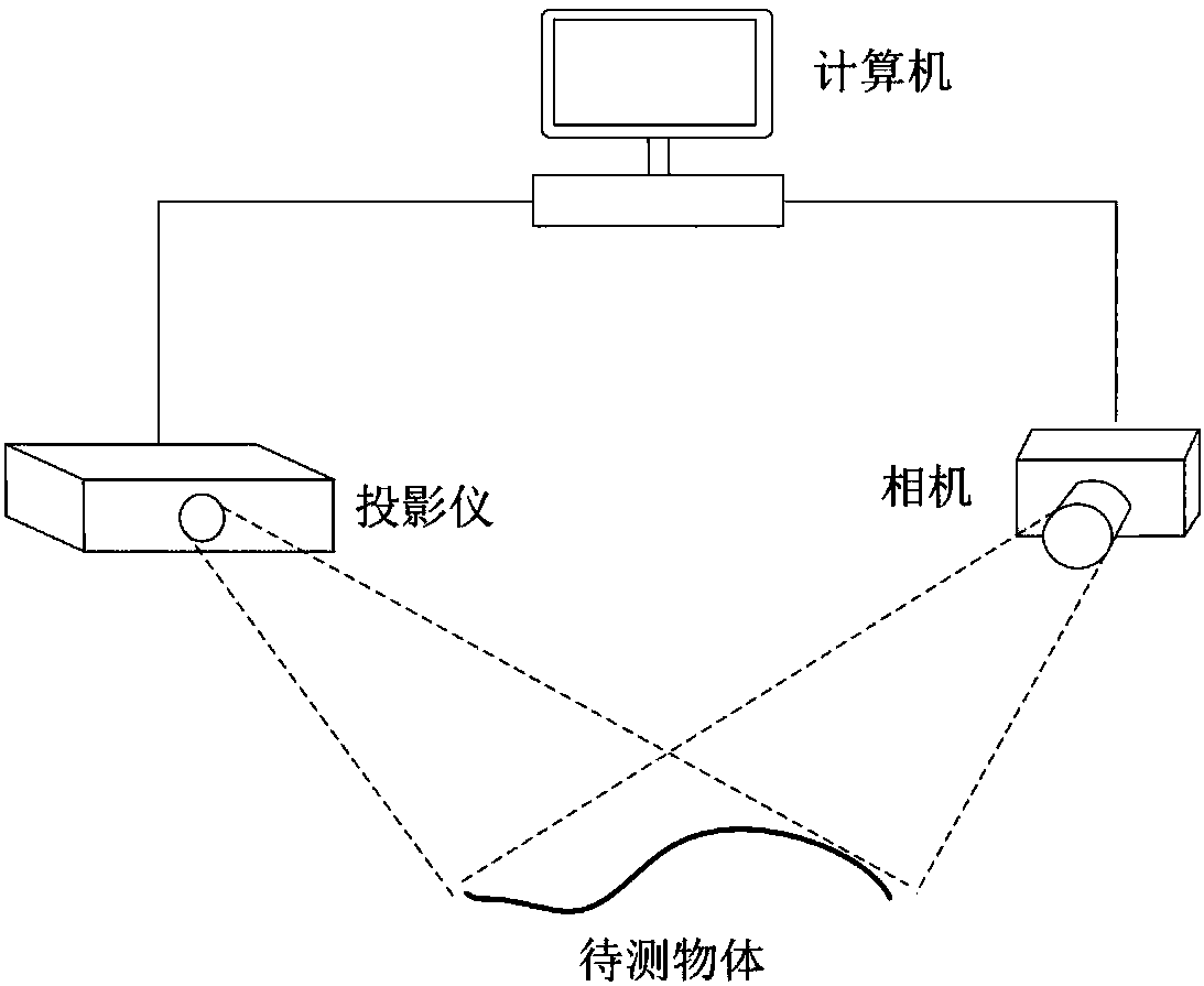
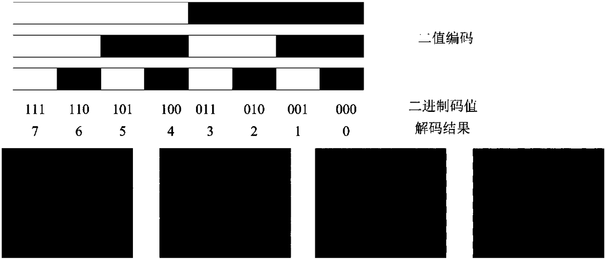
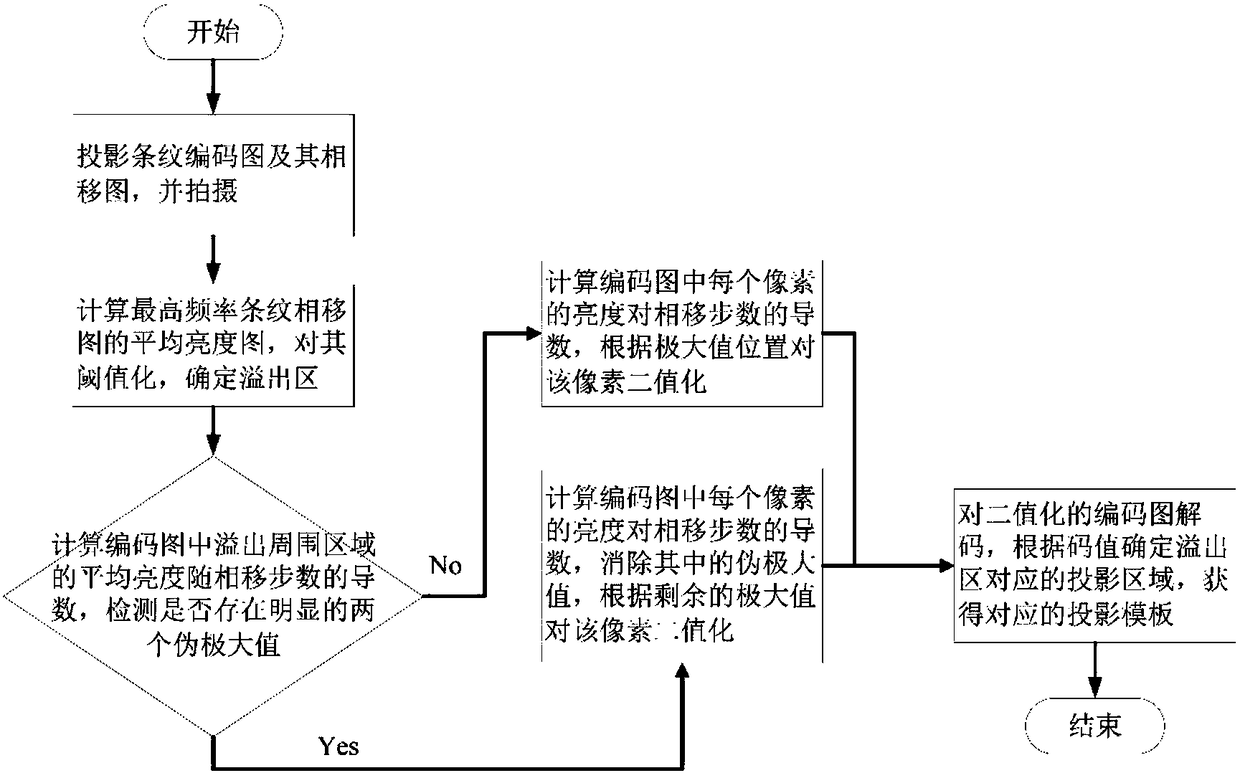
[0030] The schematic diagram of the measuring device is as figure 1 , the projection light source projects a binary coded fringe pattern and its phase shift pattern to the measured object (such as figure 2 ), calculate the average luminance map of the maximum frequency fringe phase shift map after shooting, and threshold it to determine the overflow area; then, calculate the average luminance of the area around the overflow in the encoding map, and calculate the average luminance against the phase shift step The derivative of the number, there will be two results at this time:

[0031] a. There is no pseudo-maximum value in the above derivative, but it is random, and there is no need to deal with overflow at this time;

[0032] b. When there are two obvious pseudo-maximum values, they should be eliminated because they int...


PUM


Abstract

The invention discloses an area projection optical 3D profile measuring method for an object with a high dynamic range. The method comprises steps of: projecting a two-valued encoded stripe graph and a phase shift graph thereof onto a measured object to obtain a projection template; multiplying the projection template by the corresponding pixels of a multi-frequency sine stripe phase shift graph to obtain an area projection graph; projecting the area projection graph onto the measured object again, computing a phase graph by using a phase shift algorithm, and endowing a space with an invariable reflectivity to obtain an enhanced stripe graph; and unwrapping the phase graph by using the multi-frequency stripe and restoring the phase of a shielded area line by line, and giving the reflectivity to obtain a restored stripe graph, and solving the 3D profile data of the measured object by using the stripe graph. The method uses the area projection graph, eliminates an influence of overflow on the a high dynamic range method while not increasing the complexity of a hardware system, and solves low precision of structured light 3D profile measurement of the object with a high dynamic range.

Description

technical field [0001] The invention belongs to the field of photoelectric measurement, in particular to an area projection optical three-dimensional profile measurement method for high dynamic range objects. Background technique [0002] Optical 3D profilometry technology has always been a research hotspot in the field of 3D sensing and metrology, and is widely used in industrial inspection, reverse engineering, 3D human body modeling, and cultural relic protection. Because of its non-contact, non-destructive, fast speed, high precision and other characteristics, it becomes the most ideal means of contour shape measurement. [0003] The structured light three-dimensional profilometry method demodulates the three-dimensional information of the measured object field according to the light field projected on the object and the geometric relationship between the projection system, the acquisition system and the measured object reference. In order to be suitable for the measure...

Claims


Application Information

Patent Timeline
Patent Type & Authority Patents(China)
IPC IPC(8): G01B11/25
CPCG01B11/254
Inventor 王昭齐召帅黄军辉薛琦高建民
Owner XI AN JIAOTONG UNIV
Learn More